Specialty printing device and specialty printing method

A kind of printing equipment and special technology, applied in the field of printing, can solve the problems of complicated structure, waste of hot stamping foil, etc., and achieve the effects of simple operation, high utilization rate, and convenient maintenance

Pending Publication Date: 2019-11-29
JIANGSU JIN JIA NEW PACKAGING MATERIALS CO LTD
View PDF1 Cites 2 Cited by
  • Summary
  • Abstract
  • Description
  • Claims
  • Application Information

AI Technical Summary

Problems solved by technology

[0004] The problem in this prior art is that although the waste film retracting mechanism is added to solve the problem of hot stamping foil waste to a certain extent, the structure is messy and complicated.

Method used


Image

  • Specialty printing device and specialty printing method
  • Specialty printing device and specialty printing method
  • Specialty printing device and specialty printing method

Examples


Embodiment 1

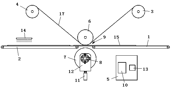
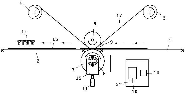
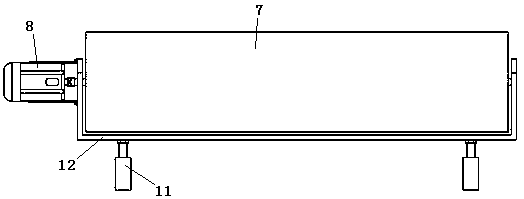
[0033] Example 1: as Figure 1~3 As shown, a special printing equipment includes a first paper feeding mechanism 1, a second paper feeding mechanism 2, a pressing mechanism, an unwinding roller 3, a winding roller 4 and a control cabinet 5; the pressing mechanism includes an upper pressure The roller 6 and the lower pressing roller 7, the first servo motor 8 drives and connects the lower pressing roller 7, the first paper feeding mechanism 1 and the second paper feeding mechanism 2 are arranged on both sides of the pressing mechanism, and the upper pressing roller 6 is close to the first There is an electronic eye 9 above this end of the paper feeding mechanism 1, and the electronic eye 9 is arranged obliquely to illuminate the tangent point of the upper pressing roller 6 and the lower pressing roller 7; the unwinding roller 3 and the winding roller 4 are arranged on the upper pressing roller 6. Above the two sides, a second servo motor (not shown in the drawings) is driven an...

Embodiment 2

[0039] Embodiment 2: a special printing method realized using the special printing equipment described in Embodiment 1,

[0040] Step 1: Before the cold stamping printing, the printing material 15 is firstly printed with UV varnish to form the information layer 16 through the screen printing equipment, and the information layer 16 protrudes from the surface of the printing material 15;

[0041] Step 2: The rolled hot stamping foil is installed on the unwinding roller 3, the foil film 17 is pulled open and passes through the bottom of the upper pressing roller 6, and is fixed on the winding roller 4;

[0042] Step ③: the printing material 15 reaches the first paper feeding mechanism 1 from the unloading end of the screen printing device, and moves to the end of the pressing mechanism through the first paper feeding mechanism 1;

[0043]Step ④: After the electronic eye 9 detects the information layer 16 on the printing material 15, it feeds back the signal to the controller 10, ...


PUM


Abstract

The invention discloses a specialty printing device and a specialty printing method. The specialty printing device comprises a first paper advancing mechanism, a second paper advancing mechanism, a pressing mechanism, an unrolling roller, a rolling roller and a control cabinet. The pressing mechanism comprises an upper pressing roller and a lower pressing roller. A first servo motor is in drive connection with the lower pressing roller. The first paper advancing mechanism and the second paper advancing mechanism are arranged on the two sides of the pressing mechanism. An electronic eye is arranged above the end, close to the first paper advancing mechanism, of the upper pressing roller. The unrolling roller and the rolling roller are arranged above the two sides of the upper pressing roller. A second servo motor is in drive connection with the rolling roller. A lifting mechanism is arranged at the bottom of the lower pressing roller so that the lower pressing roller can get away from or press the upper pressing roller. A controller is arranged in the control cabinet, and the electronic eye, the first servo motor, the second servo motor and the lifting mechanism are in signal connection with the controller. By means of the specialty printing device and the specialty printing method, the structure is reasonable, operation is simple, hot stamping foil passing through the pressingmechanism does not advance synchronously along with printed materials, the utilization rate of the hot stamping foil is higher, waste is avoided, and the expensive hot stamping foil is saved.

Description

technical field [0001] The invention relates to the technical field of printing, in particular to a special printing equipment and a special printing method. Background technique [0002] Hot stamping is a common method of surface decoration of printed matter, which is used to enhance the visual effect of labels, cartons, trademarks and other products. Hot stamping mainly includes hot stamping and cold stamping. Hot stamping is to use a metal hot stamping plate to transfer the hot stamping foil to the surface of the printing material by heating and pressing. Cold stamping usually uses ultraviolet curing varnish (also called UV varnish) to transfer the hot stamping foil to the surface of the carrier material. Compared with hot stamping, cold stamping has lower energy consumption, less equipment investment, lower plate-making cost and higher production efficiency. [0003] Chinese invention patent ZL201220603169.2 discloses a film storage device for cold stamping equipment fo...

Claims


Application Information

Patent Timeline
Patent Type & Authority Applications(China)
IPC IPC(8): B41F16/00B41F21/00B41M3/12B41M1/12
CPCB41F16/0013B41F16/006B41F16/0093B41F21/00B41M1/12B41M3/12
Inventor 董洪荣
Owner JIANGSU JIN JIA NEW PACKAGING MATERIALS CO LTD
Why Eureka
Try Eureka