
Steel reinforcement transferring device based on mine engineering construction

A mining engineering and transfer device technology, which is applied in the direction of transportation and packaging, freight vehicles, transport objects, etc., can solve the problems of poor layered storage of steel bars, affecting the unloading operation of steel bars, and affecting the use of steel bars, etc., to achieve unloading Simple and quick, improve unloading efficiency, improve the effect of loading efficiency

Inactive Publication Date: 2019-11-29
新昌县益旭龙机械科技有限公司
View PDF2 Cites 0 Cited by
  • Summary
  • Abstract
  • Description
  • Claims
  • Application Information

AI Technical Summary

Problems solved by technology

[0006] In order to solve the above-mentioned technical problems, the present invention provides a steel bar transfer device based on mine engineering construction to solve the existing similar steel bar transfer device; the layered storage effect of steel bars is poor, and the steel bars are piled up on top of each other, which is easy to affect the later stage of the steel bar The unloading operation; and the protection effect of the device is poor when transporting the steel bars, and the external rainwater is easy to adhere to the steel bars, causing corrosion of the steel bars and affecting the later use of the steel bars

Method used


Image

  • Steel reinforcement transferring device based on mine engineering construction
  • Steel reinforcement transferring device based on mine engineering construction
  • Steel reinforcement transferring device based on mine engineering construction

Examples


Embodiment

[0036] as attached figure 1 to attach Figure 11 Shown:

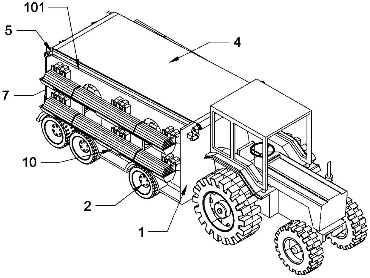
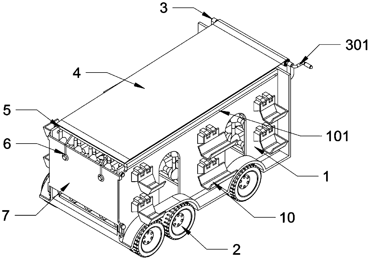
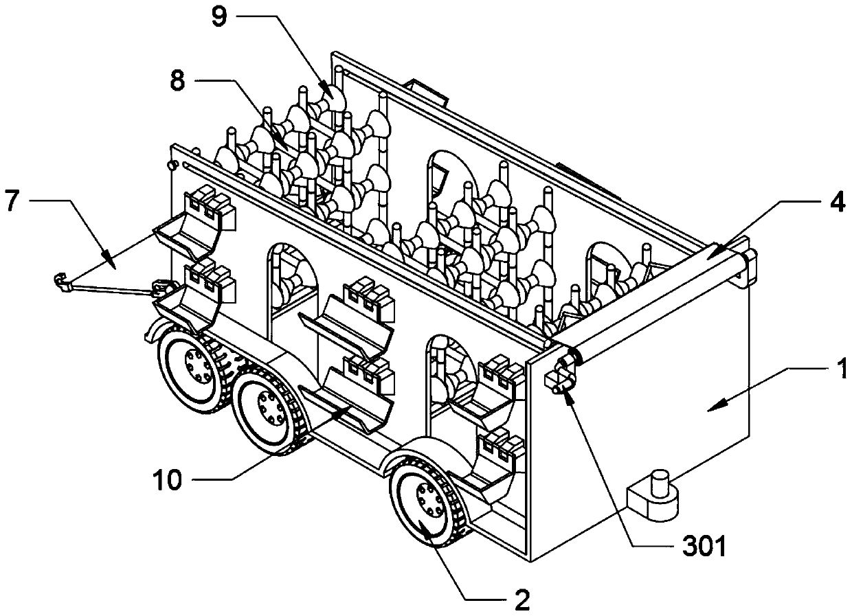
[0037] The invention provides a steel bar transfer device based on mine engineering construction, which includes a carriage 1, a sliding hole 101, a wheel 2, a rotating shaft 3, a handle 301, a canvas 4, a sliding rod 5, a lock ring 6, a tailgate 7, and a top hook 701 , the bottom hanging ring 702, the steel support frame 8, the cone block 801, the cone groove 802, the concave load-bearing runner 9 and the external hanging groove 10; the interior of the compartment 1 is hollow, and six wheels 2 are installed at the bottom of the compartment 1; One end of the rotating shaft 3 is equipped with a handle 301, and the rotating shaft 3 is installed on the top of the front end of the compartment 1; the canvas 4 is located on the top end surface of the compartment 1, and the slide bar 5 is slidably connected to the top of the compartment 1; the lock ring 6 has two place, and the two lock rings 6 are connected with the slide b...


PUM


Abstract

The invention provides a steel reinforcement transferring device based on mine engineering construction. The steel reinforcement transferring device based on mine engineering construction comprises aconcave load bearing rotating wheel and an external hanging groove; the interior of a compartment is hollow; six wheels are mounted at the bottom of the compartment; a handle is mounted at one end ofa rotating shaft; the rotating shaft is mounted at the top of the front end of the compartment; canvas is positioned on the end surface of the top of the compartment; a sliding rod is slidingly connected to the top of the compartment; two locking rings are arranged; the two locking rings are both connected with the sliding rod; the bottoms of the locking rings are hooked to the external end surface of a rear baffle; the rear baffle is of an oblong plate-shaped structure; bottom hanging rings are arranged at the left and right ends of the bottom of the rear baffle; and moreover, the bottom of the rear baffle is rotationally connected to the tail end of the compartment through the bottom hanging rings. The steel reinforcement transferring device based on mine engineering construction is beneficial for supporting bundled steel reinforcements so that the bundled steel reinforcements can be stacked in the device in a layered manner; and therefore, the transporting efficiency of the device is enhanced, the left and right ends of the bundled steel reinforcements can also be fixed to guarantee the stability of the bundled steel reinforcements during transportation.

Description

technical field [0001] The invention belongs to the technical field of mine construction, and more specifically relates to a steel bar transfer device based on mine engineering construction. Background technique [0002] With the development of the mining industry, engineering personnel will build a number of mining facilities in mining areas, and the construction of mining facilities will use a large number of steel bars, requiring professional equipment to transport the steel bars to the mining area to ensure the effect of steel bar transportation. [0003] The inventors found that the existing similar steel bar transfer device, such as the steel bar transport device mentioned in Patent Application No. 201721556635.5, includes a pair of strip-shaped bearing seats, and the left ends of the inner surfaces of the pair of strip-shaped bearing seats are fixedly connected with a No. 1 rectangular bearing plate, the center of the upper surface of the No. 1 rectangular bearing pla...

Claims


Application Information

Patent Timeline
Patent Type & Authority Applications(China)
IPC IPC(8): B60P1/52B60P7/04B60P7/135
CPCB60P1/52B60P7/04B60P7/135
Inventor 蒋益龙
Owner 新昌县益旭龙机械科技有限公司
Learn More