
Optical cabin pressure relief device

A pressure relief device and optical technology, which is applied in the laser field, can solve the problems of low pressure resistance, thin and large volume of the optical bulkhead of the laser system, and low pressure resistance, and achieve a simple, stable and reliable structure

Inactive Publication Date: 2019-11-29
INST OF APPLIED ELECTRONICS CHINA ACAD OF ENG PHYSICS
View PDF12 Cites 0 Cited by
  • Summary
  • Abstract
  • Description
  • Claims
  • Application Information

AI Technical Summary

Problems solved by technology

[0003] In addition, due to the thin and large volume of the optical bulkhead of the laser system, the relative pressure resistance is relatively low, and generally withstands 1KPa-3KPa. For such a pressure relief valve with such a low pressure resistance, there is no similar product in the market.

Method used


Image

  • Optical cabin pressure relief device
  • Optical cabin pressure relief device
  • Optical cabin pressure relief device

Examples


Embodiment 1

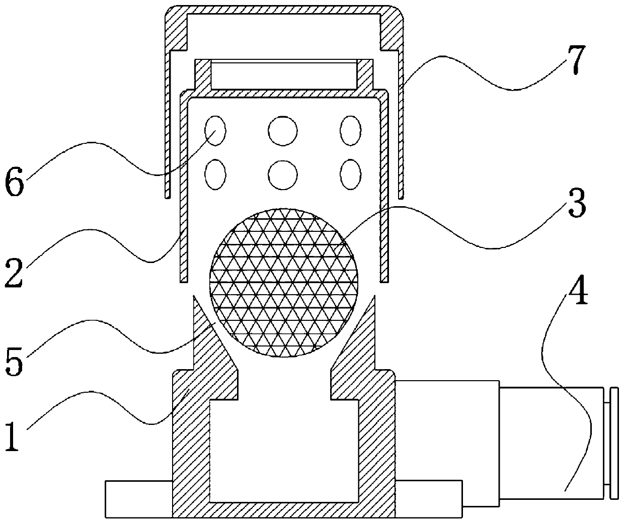
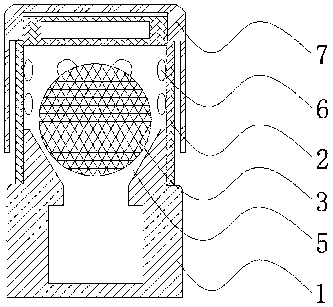
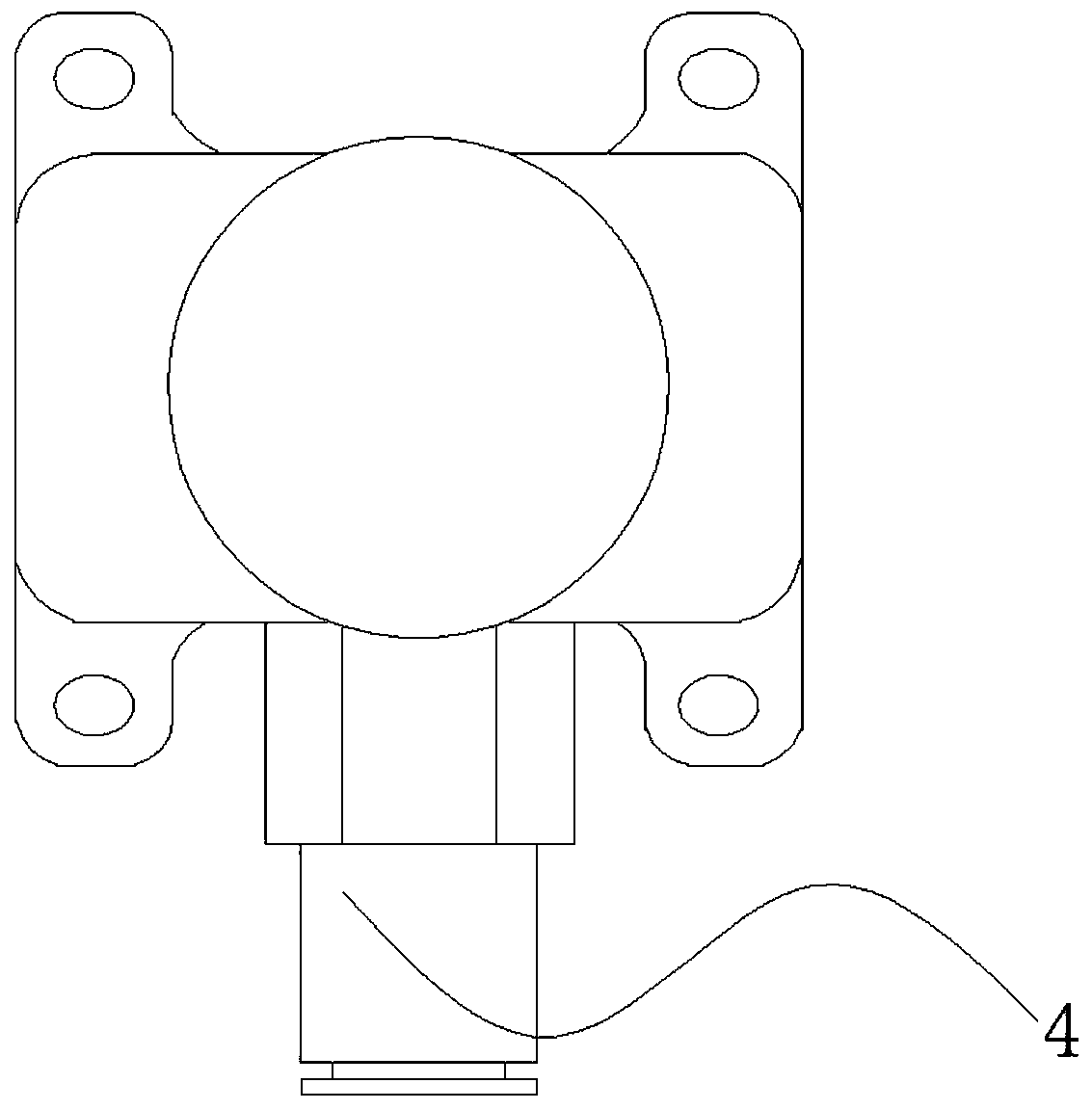
[0040] Such as Figure 2-3 As shown, an optical chamber pressure relief device of this embodiment includes an air cavity seat 1, an exhaust cover 2, a seal 3, an air nozzle joint 4 and a dust cover 7;

[0041] The top of the air cavity seat 1 is provided with an external thread column, and a tapered exhaust sealing port 5 is provided in the middle of the external thread column; the pressure-bearing floating ball is placed on the exhaust sealing port 5 and contacts with the exhaust sealing port 5 , forming a line seal on the contact surface, the seal 3 and the exhaust sealing port 5 are polished; the air cavity seat 1 is threaded with the air nozzle joint 4, the exhaust sealing port 5 communicates with the optical chamber through the air nozzle joint 4, and the air The nozzle joint 4 communicates with the optical cabin through the optical cabin exhaust hose;

[0042] The exhaust hood 2 is cylindrical, the top of the exhaust hood 2 is sealed, the bottom is open, and an exhaust ...

Embodiment 2

[0046] Such as Figure 2-3 As shown, an optical chamber pressure relief device of this embodiment includes an air cavity seat 1, an exhaust cover 2, a seal 3, an air nozzle joint 4 and a dust cover 7;

[0047] The top of the air cavity seat 1 is provided with two externally threaded columns, and the middle of the two externally threaded columns is provided with a tapered exhaust sealing port 5, and the two exhaust sealing ports 5 are connected through the cavity inside the air cavity seat 1; The pressure-bearing floating ball is placed on the exhaust sealing port 5, contacts with the exhaust sealing port 5, and forms a line seal on the contact surface, and the sealing member 3 and the exhaust sealing port 5 are all polished; The nozzle joint 4 is threaded, the exhaust sealing port 5 communicates with the optical cabin through the air nozzle joint 4, and the air nozzle joint 4 communicates with the optical cabin through the optical cabin exhaust hose;

[0048] The exhaust hood...


PUM


Abstract

The invention discloses an optical cabin pressure relief device. The optical cabin pressure relief device comprises an air cavity seat, an exhaust hood, a sealing part and an air tap joint; an exhaustsealing opening is formed in the top of the air cavity seat; the sealing part is placed in the exhaust sealing opening and is in contact with the exhaust sealing opening to form sealing on the contact surface; the exhaust hood is provided with an exhaust channel, connected with the air cavity seat and arranged in the exhaust sealing opening; and the air cavity seat is connected with the air tap joint, and the exhaust sealing opening communicates with the optical cabin through the air tap joint. The optical cabin pressure relief device is adopted, exhausting in laser system optical cabin air replacement is achieved, pressure maintaining sealing of the optical cabin after air replacement is achieved, and the pressure maintaining value can be designed; the optical cabin pressure relief device has the low-pressure resistant performance and can be suitable for the low-pressure environment; and pure mechanical structural pressure relief is adopted, electric controlling is not required, thestructure is simple, and stability and reliability are achieved.

Description

technical field [0001] The invention relates to a pressure relief device for an optical cabin, in particular to a pressure relief device for an exhaust port during gas replacement in an optical cabin of a laser system, and belongs to the technical field of lasers. Background technique [0002] The pressure relief device is an important part of the gas replacement of the optical chamber of the laser system. For laser systems, if the humidity is too high, the optical components in the optical chamber may condense, and if the cleanliness is poor, the surface of the optical components in the optical chamber may be polluted by dust. Condensation and dust pollution will cause damage to the surface film of optical components and have a destructive effect on the laser system, so the humidity and cleanliness in the optical cabin need to be controlled. Generally, the humidity is controlled by regularly injecting clean dry gas to replace the gas in the cabin. In order to ensure the cl...

Claims


Application Information

Patent Timeline
Patent Type & Authority Applications(China)
IPC IPC(8): F16K17/12F16K17/164F16K27/12
CPCF16K17/12F16K17/164F16K27/12
Inventor 尹新启雒仲祥罗佳颜宏廖原陈黎杜应磊李建民余鸿铭吴娟张永红卢飞王锋邹凯
Owner INST OF APPLIED ELECTRONICS CHINA ACAD OF ENG PHYSICS
Learn More