
Multistage heat exchange system with supplemental heat source

A heat exchange system and heat source technology, applied in indirect heat exchangers, lighting and heating equipment, etc., can solve problems such as difficulty in controlling temperature, inability to meet heating needs, and increasing the risk of environmental hazards from waste discharge.

Active Publication Date: 2019-11-29
泰州市恒达换热设备制造有限公司
View PDF6 Cites 2 Cited by
  • Summary
  • Abstract
  • Description
  • Claims
  • Application Information

AI Technical Summary

Problems solved by technology

[0002] In the prior art, in order to heat the fluid to a certain required temperature, multi-stage heat exchangers are usually used to realize the gradual increase in temperature and heating. However, in the primary heat exchange process of heat exchange, due to the large temperature difference between the cold and heat sources, the exchange After heating, the temperature of the heat source drops significantly. When the subsequent heating is carried out, the temperature will not meet the requirements and cannot meet the heating needs of the next step.
Using different waste heat sources to heat different stages can heat the next cascade heat exchanger. However, such a heating method requires the design of waste heat sources of different types and temperatures. Due to the different temperatures of waste heat sources, it is applied to multi-stage heating, it is difficult to control the temperature during actual operation
Use of different sources of waste heat increases the risk of environmental hazards from waste discharges

Method used


Image

  • Multistage heat exchange system with supplemental heat source
  • Multistage heat exchange system with supplemental heat source

Examples


Embodiment Construction

[0025] The following will clearly and completely describe the technical solutions in the embodiments of the present invention with reference to the accompanying drawings in the embodiments of the present invention. Obviously, the described embodiments are only some, not all, embodiments of the present invention. Based on the embodiments of the present invention, all other embodiments obtained by persons of ordinary skill in the art without making creative efforts belong to the protection scope of the present invention.

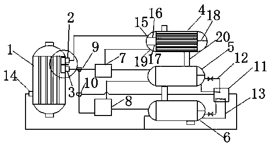
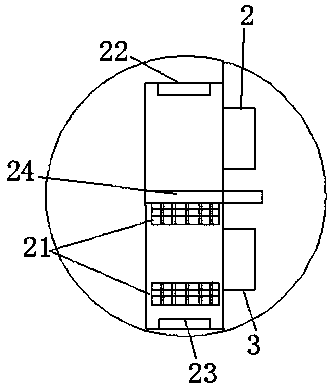
[0026] refer to Figure 1-2 , a multi-stage heat exchange system with a supplementary heat source, including a primary heating device 1, a first heat exchanger 4, a second heat exchanger 5, a third heat exchanger 6, a first mixer 7, a second mixer 8. The secondary heating device 11, the outlet I (2) of the primary heating device 1 is connected to the tube-side inlet of the first heat exchanger through a pipeline, and the upper side of the primary heating devic...


PUM


Abstract

The invention relates to a multistage heat exchange system with a supplemental heat source. By arranging the supplemental heat source, the heat source temperature of a post-stage heat exchanger of a multistage heat exchanger can be improved without increasing other external heat sources. As far as a heat exchanger which is relatively long in heat exchange tube pass is concerned, a later tube passfluid, the temperature of which does not reach the demand, can be heated in a targeted manner. Deploying supply of the heat source can be deployed freely by means of a control valve, so that the demand on different temperatures can be met. By arranging a heat source supplementation control device, the system is in a mode of accumulating heat while supplying heat when the heat source supply meets the demand on temperature. The system can be switched to a full heat supply mode when the heat source supply does not meet the demand on temperature. Heat accumulated in the early stage is supplied tothe post-stage heat exchanger to raise the temperature of the heat source, so that the demand is met.

Description

technical field [0001] The invention relates to the technical field of multi-stage heat exchange systems, in particular to a multi-stage heat exchange system with a supplementary heat source. Background technique [0002] In the prior art, in order to heat the fluid to a certain required temperature, multi-stage heat exchangers are usually used to realize the gradual increase in temperature and heating. However, in the primary heat exchange process of heat exchange, due to the large temperature difference between the cold and heat sources, the exchange After heating, the temperature of the heat source drops significantly. When the subsequent heating is carried out, the temperature will not meet the requirements and cannot meet the heating needs of the next step. Using different waste heat sources to heat different stages can heat the next cascade heat exchanger. However, such a heating method requires the design of waste heat sources of different types and temperatures. Due ...

Claims


Application Information

Patent Timeline
Patent Type & Authority Applications(China)
IPC IPC(8): F28D21/00
CPCF28D21/00
Inventor 不公告发明人
Owner 泰州市恒达换热设备制造有限公司
Learn More