
Judgment method of locked-rotor state of permanent magnet synchronous motor with position sensorless vector control

A technology of permanent magnet synchronous motor and vector control, which is applied in the control of generators, vector control systems, and electromechanical brakes, etc., and can solve the problems of low accuracy, narrow application range, and troubles in stalled state judgment

Active Publication Date: 2021-04-06
ZHONGSHAN BROAD OCEAN
View PDF2 Cites 0 Cited by
  • Summary
  • Abstract
  • Description
  • Claims
  • Application Information

AI Technical Summary

Problems solved by technology

[0009] The purpose of the present invention is to provide a method for judging the locked-rotor state of a permanent magnet synchronous motor with vector control without a position sensor, which mainly solves the problem that the accuracy of judging the locked-rotor state in the prior art is not high, the scope of application is narrow, and the control parameters do not need to be modified after the load is replaced. , more troublesome technical issues

Method used


Image

  • Judgment method of locked-rotor state of permanent magnet synchronous motor with position sensorless vector control
  • Judgment method of locked-rotor state of permanent magnet synchronous motor with position sensorless vector control
  • Judgment method of locked-rotor state of permanent magnet synchronous motor with position sensorless vector control

Examples


Embodiment Construction

[0036] The present invention will be described in further detail below through specific embodiments and in conjunction with the accompanying drawings.

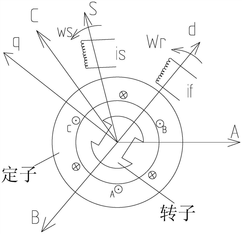
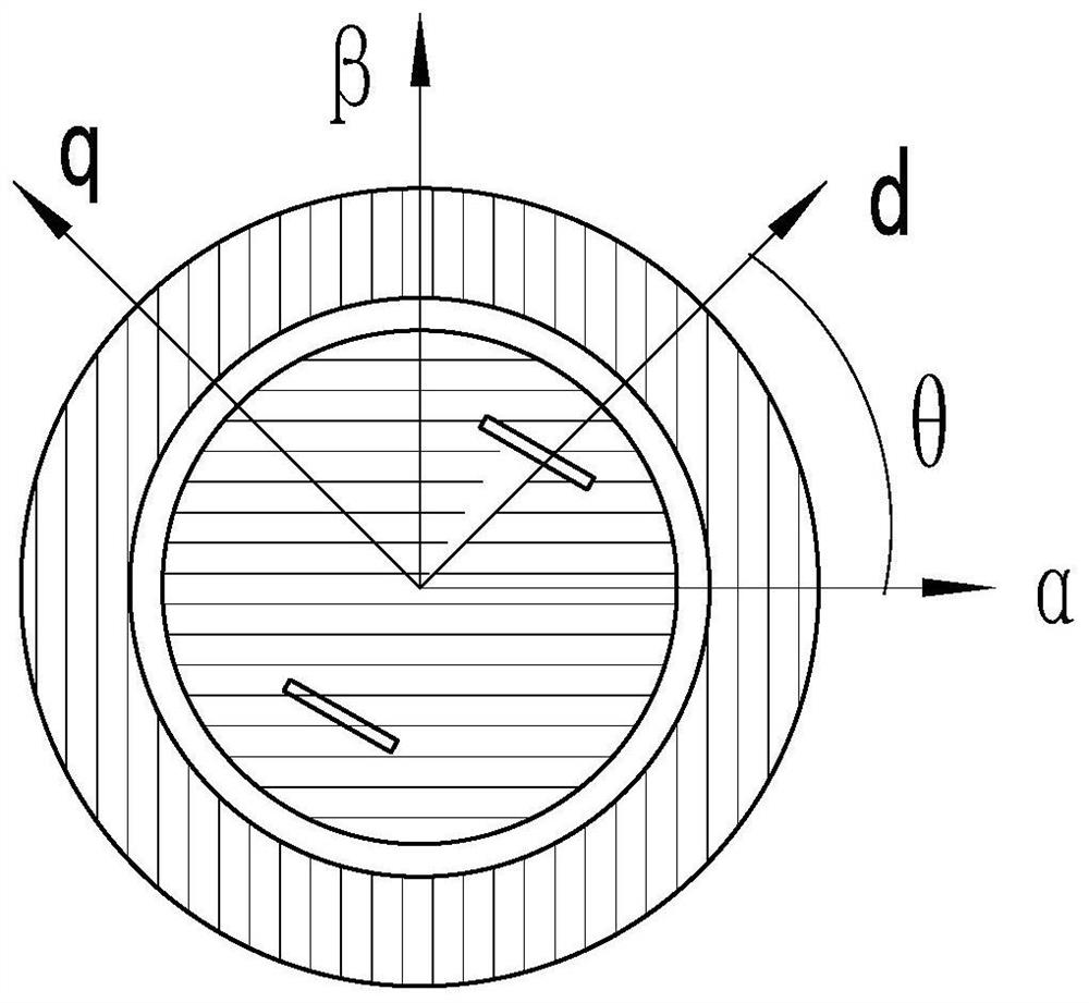
[0037] Such as figure 1 As shown, the basic working principle of the position sensorless vector control permanent magnet synchronous motor is briefly described (the textbook has a detailed description). The permanent magnet synchronous motor is regarded as the result of the interaction between the rotating magnetic field of the stator and the rotating magnetic field of the rotor. There are two There are two coordinate systems, one is the dq axis of the rotor rotating coordinate system; the other is the ABC coordinate system of the stator stationary coordinate system (which can be converted into a coordinate system perpendicular to each other in αβ); the rotor can be regarded as the role of the excitation current if rotating at the speed wr, the stator It can be regarded as the effect of the excitation current is to rotate at t...


PUM


Abstract

The invention discloses a method for judging the stalled state of a permanent magnet synchronous motor with vector control without a position sensor, which includes the following steps: step A: calculating the input power Pin and output power Pout of the motor; step B: calculating the error value ERR=|Pin‑ K1×Pout|, K1 is a coefficient; step C: judge whether ERR is greater than or equal to a certain preset value P0, if yes, return to step A; if not, judge it as a locked-rotor state, that is, it is in an abnormal closed-loop steady state , enter step D; step D: the microprocessor of the motor blocks the pulse signal output to the inverter. It can accurately judge that the motor is in a locked-rotor state, and prevent the motor from entering a stable closed-loop state when it becomes a locked-rotor state, so that the motor is in a high-frequency and small-scale oscillation state, perfecting the protection strategy, effectively protecting the motor, and fundamentally solving this blockage The problem of judging the transfer state, and it does not need to be modified after the load is replaced, which brings great convenience to the user.

Description

Technical field: [0001] The invention relates to a method for judging the locked-rotor state of a permanent magnet synchronous motor controlled by a position sensorless vector control. Background technique: [0002] The permanent magnet synchronous motor with Hall sensor can sense the rotor position and speed information through the Hall sensor at all times, so the whole control is stable and reliable, and it can also accurately judge the motor stall failure. However, the cost of the Hall sensor is high, the assembly process is complicated, and it cannot be used for a long time under harsh environmental conditions. At present, many manufacturers are gradually promoting permanent magnet synchronous motors without Hall sensors, which solves the disadvantages of Hall sensors and greatly expands the application range of permanent magnet synchronous motors. However, information such as the rotor position of the motor is obtained through complex algorithm estimation, which requir...

Claims


Application Information

Patent Timeline
Patent Type & Authority Patents(China)
IPC IPC(8): H02P21/14H02P21/24
CPCH02P21/14H02P21/24
Inventor 蓝竞豪边文清
Owner ZHONGSHAN BROAD OCEAN
Learn More