
Photovoltaic module frame

A photovoltaic module and frame technology, applied in the field of photovoltaic module frame, can solve the problems of increasing operation and maintenance cleaning costs, achieve the effects of increasing effective light receiving area, high reliability, reducing damage rate and transportation and packaging costs

Inactive Publication Date: 2019-11-29
ALPHA SOLAR SUZHOU CO LTD
View PDF5 Cites 2 Cited by
  • Summary
  • Abstract
  • Description
  • Claims
  • Application Information

AI Technical Summary

Problems solved by technology

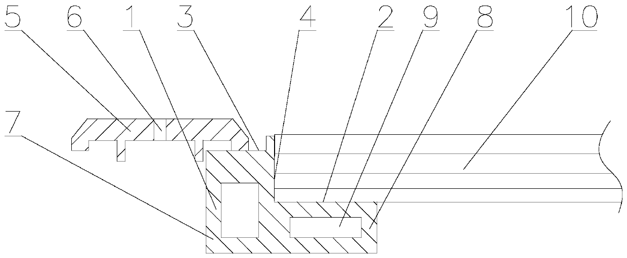
Ensure that there are no protrusions around the upper glass of the laminate, which solves the problem that the frame of the original photovoltaic module is higher than the front surface glass of the laminate, causing dust accumulation, reducing the power generation efficiency of the photovoltaic module, and increasing the cost of operation and maintenance cleaning

Method used


Image

  • Photovoltaic module frame
  • Photovoltaic module frame
  • Photovoltaic module frame

Examples


Embodiment Construction

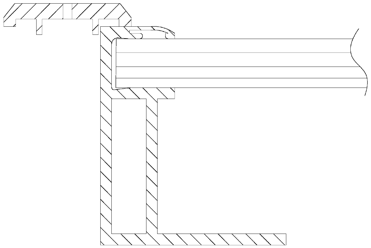
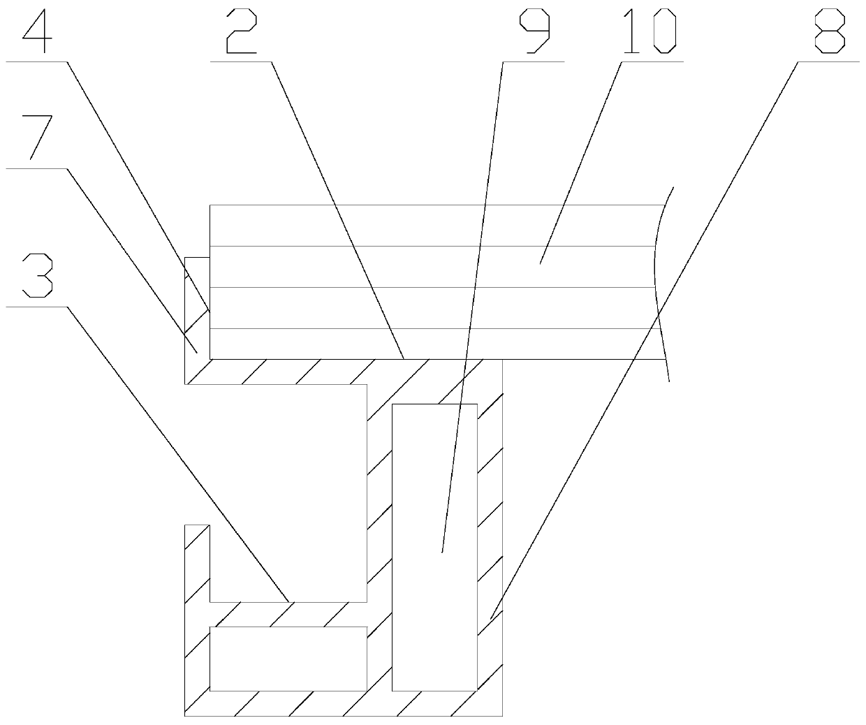
[0021] As shown in the figure, a photovoltaic module frame includes a supporting body 1, and the supporting body 1 is provided with a supporting bonding surface 2, a pressing surface 3 and a positioning surface 4; the supporting bonding surface 2 is located on the One side of the surface of the supporting body 1 is in contact with the bottom surface of the laminate of the photovoltaic module to support and bond the photovoltaic module; the positioning surface 4 is located on one side of the supporting bonding surface 2, and the The supporting adhesive surface 2 is perpendicular to the side of the photovoltaic module laminate; the press-fit surface 3 is located on one side of the positioning surface 4, and is used to connect with the pressure block 5 to fix the Support body 1.

[0022] Further, a press block 5 is provided on the press-fit surface 3, and the press block 5 is in contact with the press-fit surface 3 to press and install the entire frame structure of the photovolta...


PUM


Abstract

The invention provides a photovoltaic module frame which comprises a supporting body. A supporting and bonding surface, a pressing surface and a positioning surface are arranged on the supporting body. The supporting and bonding surface is located on one side of the surface of the supporting body and is in contact with the bottom surface of a photovoltaic module laminating member to support and bond to the photovoltaic module. The positioning surface is located on one side of the supporting and bonding surface and perpendicular to the supporting and bonding surface and is in contact with the side surface of the photovoltaic module laminating member. The pressing surface is located on one side of the positioning surface and is used for being connected with a pressing block. The photovoltaicmodule frame has the following advantages: 1, the problem of glass surface dust accumulation in the application process of the photovoltaic module in a power station is solved; 2, the light receivingarea of the photovoltaic module is effectively improved; 3, the plate damage of the photovoltaic module laminating member caused by stress concentration is eliminated and reduce the plate damage ratecaused by installation is reduced; 4, the damage rate in plate transportation is reduced and thus the transportation cost is reduced; and 5, the cleaning efficiency of the photovoltaic module in thepower station is improved and the cleaning cost is reduced.

Description

technical field [0001] The invention relates to a photovoltaic component frame. Background technique [0002] The solar photovoltaic power generation system is composed of photovoltaic modules. The front side of the photovoltaic module faces the sunlight to generate electricity. Therefore, when the photovoltaic module is installed, it needs to be supported on the assembly bracket to realize the support and stable installation of the photovoltaic module. [0003] The traditional installation structure consists of the frame of the photovoltaic module, connectors and pressure blocks (or bolts). Borders are further divided into full borders and no borders. [0004] The so-called full-frame photovoltaic module structure means that the photovoltaic module laminate is stuck in the groove on the frame, and the photovoltaic module laminate is fixed by silica gel or adhesive tape. Press the pressing block on the frame pressing surface of the photovoltaic module, and press the phot...

Claims


Application Information

Patent Timeline
IPC IPC(8): H02S30/10
CPCH02S30/10Y02E10/50
Inventor 黄子健任建丽
Owner ALPHA SOLAR SUZHOU CO LTD
Learn More