Integrated disinfectant stirring and disinfecting equipment for gynaecology and obstetrics use
A disinfectant, obstetrics and gynecology technology, applied in the field of disinfection equipment, can solve the problems of secondary pollution, large amount of disinfectant, etc., and achieve the effect of speeding up the efficiency
- Summary
- Abstract
- Description
- Claims
- Application Information
AI Technical Summary
Problems solved by technology
Method used
Image
Examples
specific Embodiment approach 1
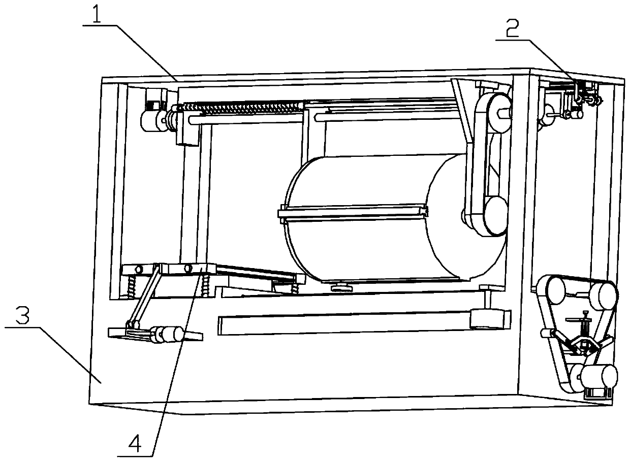
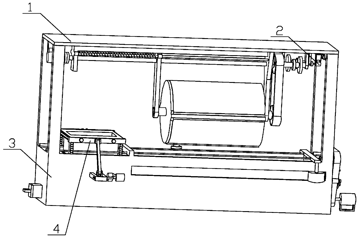
[0046] Combine below figure 1 , figure 2 , image 3 , Figure 4 , Figure 5 , Figure 6 , Figure 7 , Figure 8 , Figure 9 , Figure 10 , Figure 11 , Figure 12 , Figure 13 , Figure 14 , Figure 15 , Figure 16 , Figure 17 , Figure 18 , Figure 19 , Figure 20 , Figure 21 , Figure 22 , Figure 23 , Figure 24 , Figure 25 , Figure 26 , Figure 27 , Figure 28 , Figure 29 , Figure 30 To illustrate this embodiment, the present invention relates to a disinfection device, more specifically, an integrated equipment for mixing and disinfecting obstetrics and gynecology disinfectants, including a pull-out roller mechanism 1, an adjustable-speed driving mechanism 2, a soaking and disinfection mechanism 3, Shake the box mechanism 4, the equipment can filter while stirring the disinfectant, the equipment can adjust the stirring speed, the equipment can release the disinfectant mixture, the equipment can be soaked and disinfected, the equipment can ...
specific Embodiment approach 2
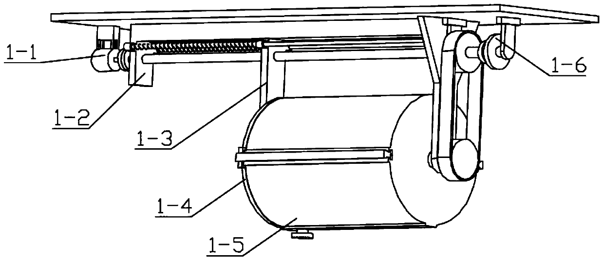
[0049] Combine below figure 1 , figure 2 , image 3 , Figure 4 , Figure 5 , Figure 6 , Figure 7 , Figure 8 , Figure 9 , Figure 10 , Figure 11 , Figure 12 , Figure 13 , Figure 14 , Figure 15 , Figure 16 , Figure 17 , Figure 18 , Figure 19 , Figure 20 , Figure 21 , Figure 22 , Figure 23 , Figure 24 , Figure 25 , Figure 26 , Figure 27 , Figure 28 , Figure 29 , Figure 30Describe this embodiment, this embodiment will further explain the first embodiment, the pull-out roller mechanism 1 includes a pull-out drive mechanism 1-1, a support frame mechanism 1-2, a movable seat mechanism 1-3, and a movable filter screen Plate mechanism 1-4, cylinder body mechanism 1-5, transmission mechanism 1-6, the drive mechanism 1-1 is pulled open to connect with the support frame mechanism 1-2, and the movable seat mechanism 1-3 cooperates with the support frame mechanism 1-2 , the movable seat mechanism 1-3 is connected with the movable filter ...
specific Embodiment approach 3
[0051] Combine below figure 1 , figure 2 , image 3 , Figure 4 , Figure 5 , Figure 6 , Figure 7 , Figure 8 , Figure 9 , Figure 10 , Figure 11 , Figure 12 , Figure 13 , Figure 14 , Figure 15 , Figure 16 , Figure 17 , Figure 18 , Figure 19 , Figure 20 , Figure 21 , Figure 22 , Figure 23 , Figure 24 , Figure 25 , Figure 26 , Figure 27 , Figure 28 , Figure 29 , Figure 30 Describe this embodiment, this embodiment will further explain Embodiment 1, the described speed-adjustable driving mechanism 2 includes a speed-regulating sliding seat mechanism 2-1, a driving mechanism 2-2, an adjusting handwheel mechanism 2-3, a lifting limit Position mechanism 2-4, limit pop-up block mechanism 2-5, speed regulating sliding seat mechanism 2-1 cooperate with driving mechanism 2-2, driving mechanism 2-2 meshes with adjusting handwheel mechanism 2-3, release The limit mechanism 2-4 is connected with the adjustment handwheel mechanism 2-3, and...
PUM
 Abstract
Description
Claims
Application Information
 - R&D
- Intellectual Property
- Life Sciences
- Materials
- Tech Scout
- Unparalleled Data Quality
- Higher Quality Content
- 60% Fewer Hallucinations
Browse by: Latest US Patents, China's latest patents, Technical Efficacy Thesaurus, Application Domain, Technology Topic, Popular Technical Reports.
© 2025 PatSnap. All rights reserved.Legal|Privacy policy|Modern Slavery Act Transparency Statement|Sitemap|About US| Contact US: help@patsnap.com


