
Deburring assembly and method

A deburring and component technology, applied in the direction of components with teeth, gear teeth, gear cutting machines, etc., can solve the problems of affecting the installation and matching accuracy of gears, low production efficiency, increase production costs, etc., to improve the use accuracy and use. effect of life

Pending Publication Date: 2019-12-03
维亚渔具(珠海)有限公司
View PDF0 Cites 0 Cited by
  • Summary
  • Abstract
  • Description
  • Claims
  • Application Information

AI Technical Summary

Problems solved by technology

[0003] In the process of gear hobbing, the tooth part of the workpiece after gear hobbing will form burrs at the step position or end of the tooth part due to the cutting flow direction of the hob, which will affect the installation and fit accuracy of subsequent gears
[0004] In order to remove the burrs, the traditional method is to use a blade to manually remove the burrs, which greatly increases the labor intensity, low production efficiency, and increases production costs
[0005] There is also a post-turning method to remove the burrs on the modified end face. Although the degree of automation has been improved, the deburring process is separated independently, which increases the process operations. The cost of labor, auxiliary materials, tooling and equipment is inevitable, and it is easy to cause rolling during the production process. Good teeth are bruised, increasing the defect rate

Method used


Image

  • Deburring assembly and method
  • Deburring assembly and method
  • Deburring assembly and method

Examples


Embodiment Construction

[0053] This part will describe the specific embodiment of the present invention in detail, and the preferred embodiment of the present invention is shown in the accompanying drawings. Each technical feature and overall technical solution of the invention, but they should not be understood as limiting the protection scope of the present invention.

[0054] In the description of the present invention, it should be understood that the orientation descriptions, such as up, down, front, back, left, right, etc. indicated orientations or positional relationships are based on the orientations or positional relationships shown in the drawings, and are only In order to facilitate the description of the present invention and simplify the description, it does not indicate or imply that the referred device or element must have a specific orientation, be constructed and operated in a specific orientation, and thus should not be construed as limiting the present invention.

[0055]In the des...


PUM


Abstract

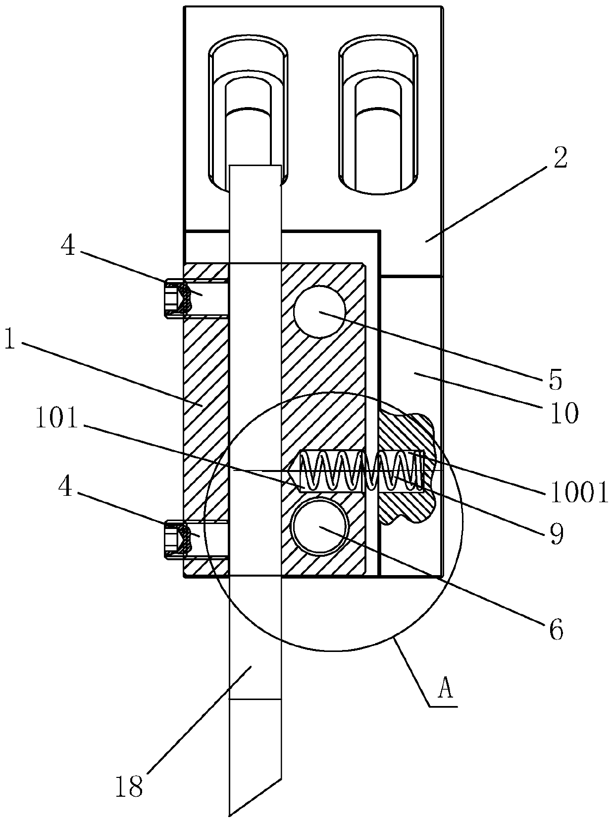
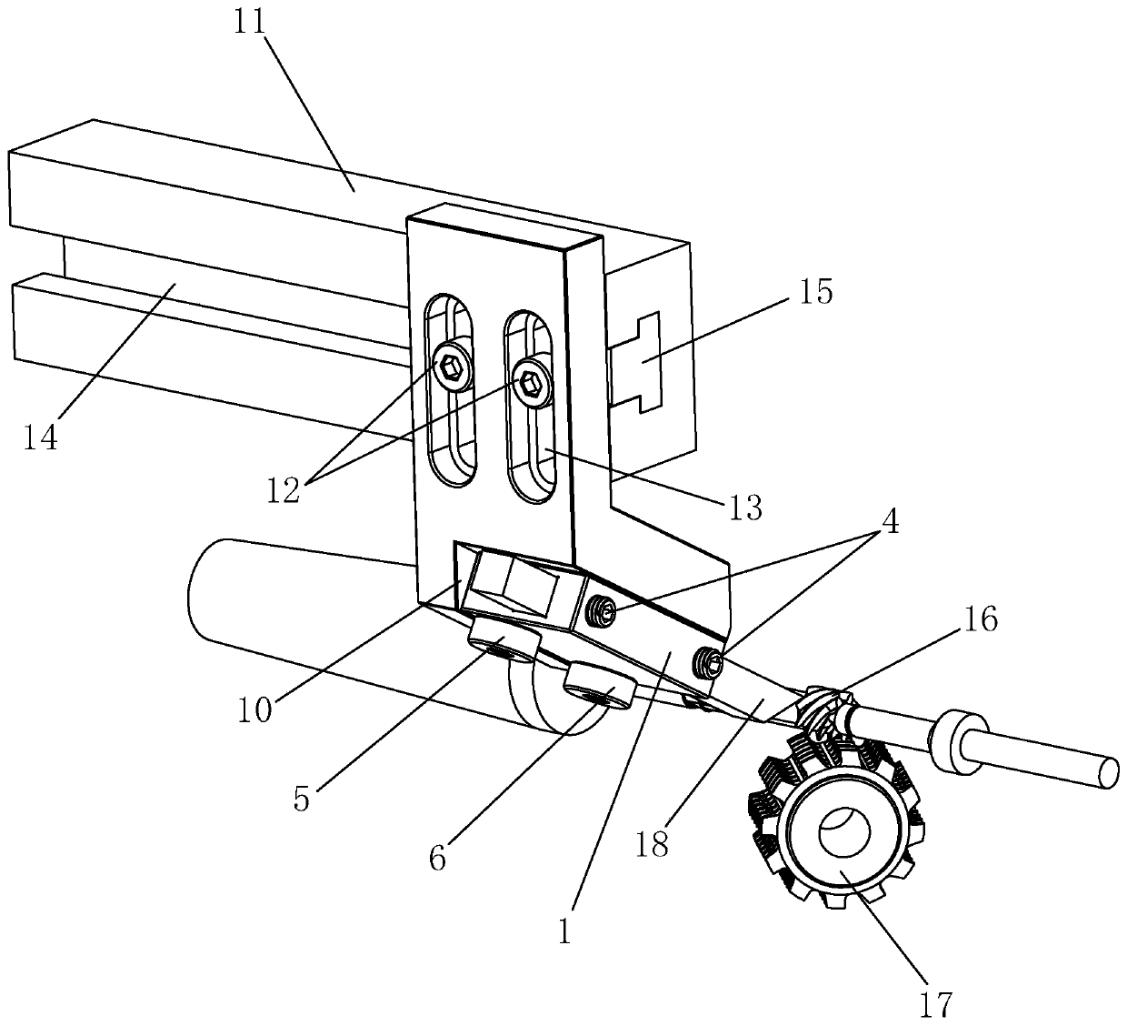
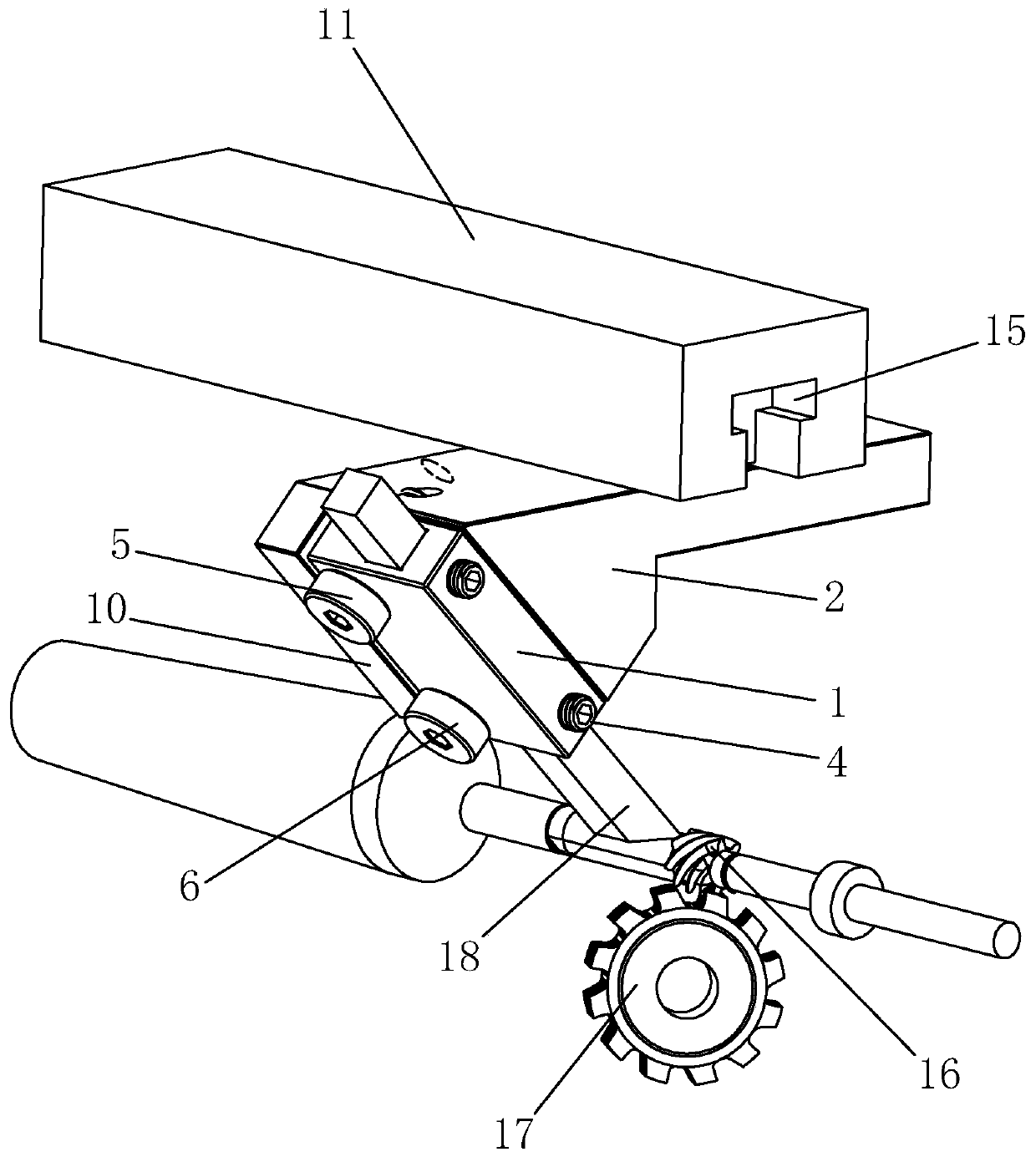
The invention belongs to the field of machining, and discloses a deburring assembly in order to effectively remove burrs in hobbing. The deburring assembly comprises a mounting seat for mounting a cutter; a connecting seat, wherein the mounting seat is rotatably arranged on the connecting seat; a corner limiting device which is used for limiting the rotating angle range of the mounting seat relative to the connecting seat; and an elastic pre-tightening device which enables the connecting seat to be located at the end point of any side of the corner range in an elastic pressing or elastic stretching mode. The invention further discloses a deburring method. A cutter is arranged in the mounting seat. The mounting seat is moved to enable the cutter to be located at the burr generation positionof the workpiece in the hobbing process; the part, where the burs are generated, of the workpiece extrudes the cutter, and the mounting seat rotates relative to the connecting seat within a rotatingangle limited by the corner limiting device under the reverse action of elastic pre-tightening force of the elastic pre-tightening device; during machining or after machining, the workpiece rotates, and burrs are scraped off by the cutter. Burrs can be efficiently and synchronously removed, and workpieces are not prone to damage.

Description

technical field [0001] The invention relates to the field of workpiece processing, in particular to a deburring component and method. Background technique [0002] The gear hobbing process is to process the gear through the principle of the generation method. The generation method is also called the Fan Cheng method, which is a method of cutting out the tooth shape by using the meshing motion of the gear tool and the tooth blank. [0003] During the hobbing process, the hobbed teeth of the workpiece will form burrs at the step position or end of the gear due to the cutting flow direction of the hob, which will affect the installation and fit accuracy of the subsequent gears. [0004] In order to remove the burrs, the traditional method is to use a blade to manually remove the burrs, which greatly increases the labor intensity, reduces production efficiency, and increases production costs. [0005] There is also a method of post-turning to remove the burr on the modified end...

Claims


Application Information

Patent Timeline
Patent Type & Authority Applications(China)
IPC IPC(8): B23F19/00B23F23/12
CPCB23F19/00B23F23/1237
Inventor 彭建明
Owner 维亚渔具(珠海)有限公司
Learn More