Flash removing punch die and flash removing method for plastic package belt of chip tantalum capacitor

A chip-type tantalum capacitor technology, which is used in the field of flash removal dies and flash removal for chip tantalum capacitors. Unclean and other problems, to achieve the effect of not easy to deform the strip, reduce labor intensity, and have good consistency

Inactive Publication Date: 2019-12-03
CHINA ZHENHUA GRP XINYUN ELECTRONICS COMP ANDDEV CO LTD
View PDF7 Cites 0 Cited by
  • Summary
  • Abstract
  • Description
  • Claims
  • Application Information

AI Technical Summary

Problems solved by technology

[0002] Nowadays, all kinds of electronic equipment or devices are widely used in all aspects of people's daily life and work. These electronic equipment or devices need to use a large number of electronic components. Chip tantalum capacitors are a common type of electronic components. Tantalum capacitors are highly integrated and have small dimensions. Usually, multiple chip tantalum capacitors are plastic-packed on a strip. However, in the process of plastic-packing chip tantalum capacitors, the feed inlet is usually made of the gap in the strip. material, resulting in plastic sealing, the strip retains the material inlet, exhaust outlet overflow
It is difficult to remove and the removal is not clean, which affects the production quality of the later process. In the prior art, manual operations are still used to remove the flashing of the chip tantalum capacitor plastic tape. The operator holds the chip with a tool such as a bamboo chip Type tantalum capacitors are plastic-sealed with flash scraping. This operation method is extremely inefficient and labor-intensive, and the flash cannot be completely removed.

Method used


Image

  • Flash removing punch die and flash removing method for plastic package belt of chip tantalum capacitor
  • Flash removing punch die and flash removing method for plastic package belt of chip tantalum capacitor

Examples


Embodiment Construction

[0021] The technical solution of the present invention is further described below, but the scope of protection is not limited to the description.

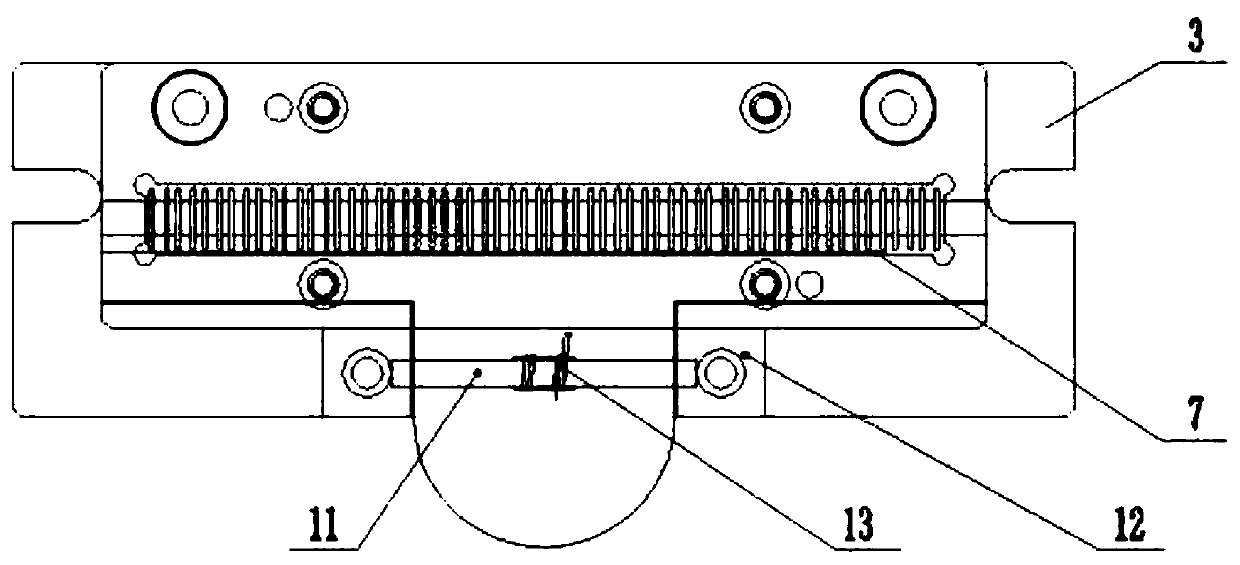
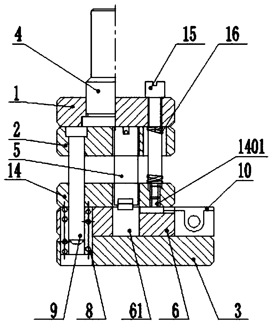
[0022] The present invention provides a chip type tantalum capacitor plastic seal tape overflow removal punching die, such as figure 1 , figure 2 As shown, it includes an upper template 1, a lower template 2 and a base 3. The upper template 1 and the lower template 2 are overlapped and fixedly connected together. The upper template 1 is fixedly connected with a punch handle 4, and the upper template 2 is fixedly connected. There is a convex mold 5, and a concave mold 6 is fixedly connected on the base 3, and a mold hole 61 is arranged on the concave mold 6, and the convex mold 5 can fit in the mold hole 61. The punch handle 4 is conveniently connected with corresponding power devices such as stamping equipment, and by using automatic equipment instead of manually scraping off the overflow, labor costs and labor intensity are redu...


PUM


Abstract

The invention provides a flash removing punching die and a flash removing method for a plastic package belt of a chip tantalum capacitor. The flash removing punch die comprises an upper die plate, alower die plate and a base, the upper die plate and the lower die plate are mutually overlapped and fixedly connected together, a punch handle is fixedly connected to the upper die plate, a male die is fixedly connected to the lower die plate, a female die is fixedly connected to the base, a die hole is formed in the female die, and the male die can be sleeved in the die hole. The flash removing method comprises the following steps: providing power through stamping equipment, and blanking to remove flash of the plastic package belt of the chip tantalum capacitor. The technical scheme of the invention is adopted; the male die and the female die are driven to be sleeved with each other through power provided by the stamping equipment, the flash of the plastic package belt of the chip tantalum capacitor can be removed rapidly and cleanly, deformation of the plastic package belt is avoided, operation is easy and convenient, the labor cost is reduced, the labor intensity is relieved, the plastic package efficiency of the chip tantalum capacitor is improved, and the production quality is improved.

Description

technical field [0001] The invention relates to the technical field of tantalum capacitor packaging, in particular to a chip-type tantalum capacitor plastic package flash removal die and a flash removal method. Background technique [0002] Nowadays, all kinds of electronic equipment or devices are widely used in all aspects of people's daily life and work. These electronic equipment or devices need to use a large number of electronic components. Chip tantalum capacitors are a common type of electronic components. Tantalum capacitors are highly integrated and have small dimensions. Usually, multiple chip tantalum capacitors are plastic-packed on a strip. However, in the process of plastic-packing chip tantalum capacitors, the feed inlet is usually made of the gap in the strip. After the plastic seal is formed, the material inlet and exhaust outlet are left on the strip. It is difficult to remove and the removal is not clean, which affects the production quality of the later...

Claims


Application Information

Patent Timeline
Patent Type & Authority Applications(China)
IPC IPC(8): B26F1/44B26F1/40B26D7/32
CPCB26D7/32B26F1/40B26F1/44
Inventor 黎建平孙大贵常开银吴鹏李露雷军倪志伟陈立
Owner CHINA ZHENHUA GRP XINYUN ELECTRONICS COMP ANDDEV CO LTD
Why Eureka
Try Eureka