A remote control charging pile based on Internet of Things technology

An Internet of Things technology and remote control technology, which is applied in the field of remote control charging piles, can solve the problems of shortening the service life of the battery board, damping the battery board, short circuit, etc., and achieve the effect of convenient operation, prolonging the service life and avoiding short circuit

Active Publication Date: 2020-10-13
NANJING GREEN NEW ENERGY RES INST CO LTD
View PDF1 Cites 0 Cited by
  • Summary
  • Abstract
  • Description
  • Claims
  • Application Information

AI Technical Summary

Problems solved by technology

The utility model simultaneously solves the technical problems that the current utilization of solar energy is not reasonable enough, and it is inconvenient for remote users to operate
[0004] There is no storage device for the solar panel in the above technical solution, so when it encounters rainy weather, it will easily cause the panel to be damp and cause a short circuit problem, which greatly shortens the service life of the panel, so we propose a solution based on the Internet of Things The remote control charging pile of technology is used to solve the problems raised above

Method used


Image

  • A remote control charging pile based on Internet of Things technology
  • A remote control charging pile based on Internet of Things technology
  • A remote control charging pile based on Internet of Things technology

Examples


Embodiment 1

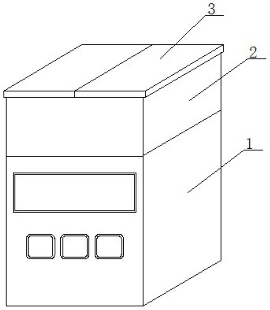
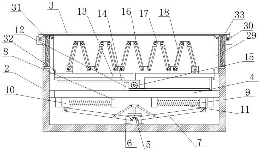
[0031] see Figure 1-5 , this embodiment provides a remote control charging pile based on Internet of Things technology, including a charging pile 1, a storage box 2 is fixedly installed on the top of the charging pile 1, and a cover plate 3 is mounted on the top of the storage box 2, and the storage box 2 is slidingly connected with a moving plate 4, and the top of the moving plate 4 is provided with a plurality of mounting frames 16, and the multiple mounting frames 16 are connected to each other in rotation, and a battery board 18 is fixedly installed on the mounting frame 16, and the top of the moving plate 4 slides symmetrically Two receiving plates 13 are connected, and the mounting brackets 16 on both sides are respectively connected to the tops of the two receiving plates 13 for rotation, the bottom of the receiving plates 13 is fixedly equipped with connecting plates 12, and the bottoms of the two connecting plates 12 are connected to The top of the moving plate 4 is ...

Embodiment 2

[0034] see Figure 1-5 , further improvements have been made on the basis of Example 1:

[0035] A plurality of hinged plates 17 are arranged on the top of the movable plate 4, and both sides of the hinged plates 17 are provided with rotating ports, and the mounting shafts 20 are rotationally connected in the rotating ports, and the mounting brackets 16 are respectively fixedly sleeved on the corresponding two mounting shafts. 20 on.

[0036] Two torsion springs 21 are sheathed on the installation shaft 20, and the two ends of the torsion springs 21 are respectively fixedly connected to one side of the installation frame 16 and the inner wall of one side of the rotating opening.

[0037] A slide plate 25 is slidably connected to the top of the moving plate 4, a ball screw 24 is fixedly installed on one side of the slide plate 25, a ball screw nut 22 is fixedly installed on the inner wall of the gear 15, and one end of the ball screw 24 runs through the ball screw nut 22 And ...


PUM


Abstract

The invention discloses a remote control charging pile based on Internet of Things technology, comprising a charging pile, a storage box is fixedly installed on the top of the charging pile, and a cover plate is mounted on the top of the storage box, and the inside of the storage box is slidingly connected There is a moving plate, the top of the moving plate is provided with a plurality of mounting frames, and the multiple mounting frames are connected to each other in rotation, the battery board is fixedly installed on the mounting frame, and the top of the moving plate is symmetrically slidingly connected with two storage board, and the mounting brackets on both sides are respectively connected to the tops of the two storage boards in rotation. In the present invention, multiple battery panels can be folded by starting the rotating motor, and then multiple battery panels can be transferred to the storage box by starting the push rod motor, so as to achieve the purpose of storing the battery panels, and the operation is relatively convenient. The battery board can be protected from rainwater interference, avoiding the short circuit problem of the battery board, and can effectively prolong the service life of the battery board.

Description

technical field [0001] The invention relates to the technical field of charging piles, in particular to a remote-controlled charging pile based on Internet of Things technology. Background technique [0002] The function of the charging pile is similar to the refueling machine in the gas station. It can be fixed on the ground or wall, and installed in public buildings (public buildings, shopping malls, public parking lots, etc.) and residential area parking lots or charging stations. Charge all models of electric vehicles. [0003] Announcement number: CN207015181U discloses a solar remote control charging pile, including a housing, and a charging control circuit board capable of transmitting a charging two-dimensional code to a remote device is installed in the housing, and the charging control circuit board is electrically connected to a charging plug for charging ;The front of the housing is provided with an IC card reader connected to the charging control circuit board;...

Claims


Application Information

Patent Timeline
Patent Type & Authority Patents(China)
IPC IPC(8): B60L53/31B60L53/68
CPCB60L53/31B60L53/68Y02T90/167Y02T90/16Y02T10/70Y02T10/7072Y02T90/12Y04S30/12
Inventor 贾艳刚刘海洋张秋月王飞
Owner NANJING GREEN NEW ENERGY RES INST CO LTD
Why Eureka
Try Eureka