
Detachable floating platform artificial wave making device and method

A floating platform, detachable technology, applied in the field of public sports and entertainment auxiliary facilities, can solve the problems of unmanufacturable, unusable, high cost of track construction, etc.

Pending Publication Date: 2019-12-03
INST OF ELECTRICAL ENG CHINESE ACAD OF SCI
View PDF0 Cites 4 Cited by
  • Summary
  • Abstract
  • Description
  • Claims
  • Application Information

AI Technical Summary

Problems solved by technology

This fixed track also brings big problems: 1. At present, most of the tracks are reinforced concrete and steel truss structures. After the track is completed, the height and length are fixed, and the depth of the pool cannot be changed. Because of tides, rainfall and evaporation, runoff, wet seasons and dry seasons, etc., the water depth is constantly changing. The track with a fixed height will be submerged and cannot be used when the water is deep, or cannot create effective waves when the water is shallow. In order to maintain stability The existing technology has to invest in water supply and drainage systems to maintain the stability of the water level; 2. In order to withstand the gravity of the block or wave maker itself, the impact of starting and braking, and the reaction from the water, the track must be designed and constructed Form a very thick reinforced concrete structure and lay a deep and wide foundation. Such a wave-making device will be defined as a permanent building in architecture. It is not allowed to be used in many land-based plot areas, and it is difficult to pass the certification of the EIA. ; 3. The cost of track construction will be very high

Method used


Image

  • Detachable floating platform artificial wave making device and method
  • Detachable floating platform artificial wave making device and method
  • Detachable floating platform artificial wave making device and method

Examples


Embodiment Construction

[0026] The main purpose of the present invention is to solve the problem that the current outdoor large-scale artificial wave-making equipment has a huge single investment, can only be operated in a permanent fixed position, and has a low utilization rate due to factors such as climate. For example, the artificial wave pool built in the north of my country can no longer be used after entering the winter freezing period, and the freezing will seriously damage the equipment. However, in the south of the Yangtze River in my country, the summer is relatively hot and humid, which is not as cool and pleasant as the northern coastal areas. Therefore, if The artificial wave-making device can be like a migratory bird, which can migrate along the coast of our country or in inland waters connected by rivers and waterways, which will greatly increase the utilization rate of the device, and it will be used in different coastal cities or regions along the river. The benefits are much better th...


PUM


Abstract

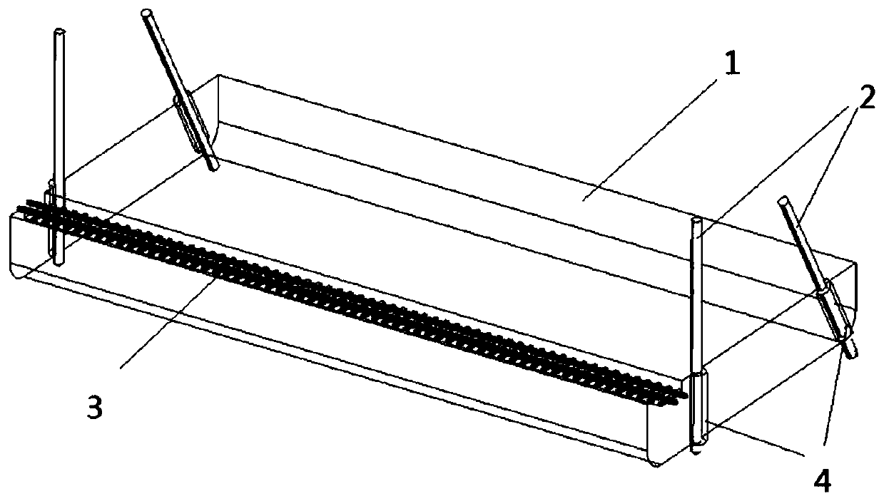
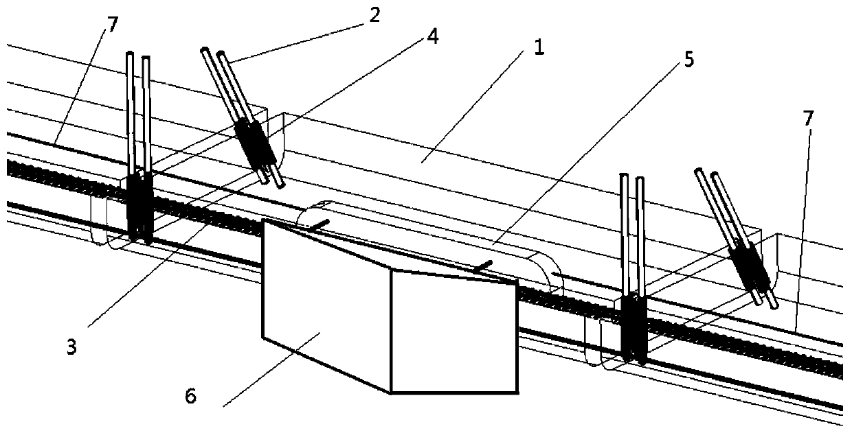
The invention relates to a detachable water floating platform artificial wave making device and method. A floating platform comprises a plurality of floating rectangular box bodies; each box body canfloat on the water surface, vertical or inclined supporting columns are mounted, and the supporting columns and the box bodies can move and be fixed relatively through connecting cylinders. The bottomends of the supporting columns can be supported on the water bottom to ensure that the box bodies are fixed relatively; or if necessary, the supporting columns are extracted from the water, and the box bodies are released. The box bodies are connected end to end to form the long floating platform, and are fixed by connecting pieces, tracks carried on the box bodies are in linear butt joint with one another, and a wave maker reciprocates along the tracks to make waves in a water pool. When the supporting columns are lifted from the water, the box bodies are released and enter a floating state,the connecting pieces among the box bodies are released, the box bodies are separated from one another, each box body can be dragged away by a powered ship to be transferred to a next designated position, and then the box bodies are remounted to carry out artificial wave making work.

Description

technical field [0001] The invention relates to a detachable platform-type artificial wave-making device and method for floating on water, which can be moored on the water surface to artificially generate waves, and the platform automatically rises and falls with the change of water depth, and belongs to the wave environment adaptability test platform of warships and wave power generation Equipment testing, as well as the category of public sports and entertainment auxiliary facilities. Background technique [0002] Surfing became an Olympic event in 2016, and more and more countries and regions, including China, began to promote and popularize surfing. In order to overcome defects such as insufficient and unstable wave sources in nature, people have developed a variety of artificial wave-making devices. There are push plate type, vacuum type, air pressure type, etc. These kinds of artificial wave-making devices have a common feature that once the wave is formed, in the proc...

Claims


Application Information

Patent Timeline
IPC IPC(8): E04H4/00E02B17/00B63B35/44
CPCE04H4/0006E02B17/00B63B35/44E02B2017/0056
Inventor 王厚生陈京亮李仲一李瑞林
Owner INST OF ELECTRICAL ENG CHINESE ACAD OF SCI
Learn More