Mixed flow fan

A mixed-flow fan and current collector technology, which is applied in the direction of mechanical equipment, machines/engines, liquid fuel engines, etc., can solve the problems of weakening the working ability of the impeller, and achieve the effects of small product size, reduced flow resistance, and reasonable scheme

Active Publication Date: 2019-12-03
XI AN JIAOTONG UNIV
View PDF8 Cites 5 Cited by
  • Summary
  • Abstract
  • Description
  • Claims
  • Application Information

AI Technical Summary

Problems solved by technology

For high-pressure mixed-flow fans with a large change in the diameter of the impeller inlet and outlet, the arc-shaped case line and the hub line exit are axial, so the angle between the inlet and the shaft is relatively large, and after the airflow flows into the impeller, it is easy to form a low-speed vortex zone in the case , weaken the impeller's ability to work

Method used


Image

  • Mixed flow fan
  • Mixed flow fan

Examples


Embodiment Construction

[0031] The present invention is further described below in conjunction with accompanying drawing:

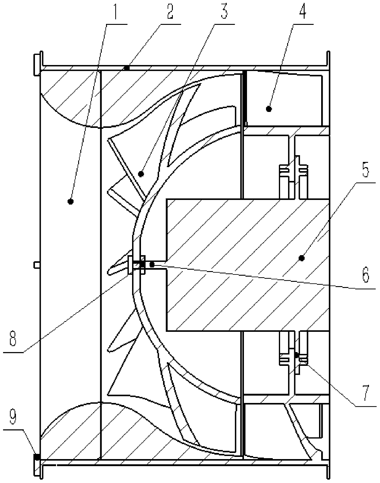
[0032] see figure 1 and figure 2 , a mixed-flow fan, including a motor 5, a casing 2, an impeller 3, a guide vane 4 and a collector 1; the inside of one end of the casing 2 is coaxially fixed with a guide vane 4, and the motor 5 is arranged on the hub of the guide vane 4 The center; the output shaft of the motor 5 is fixedly connected to the center of the impeller 3; the other end of the casing 2 is provided with a current collector 1 on the same side as the impeller 3; the diameter of the hub of the guide vane 4 is the same as that of the impeller 3 ;

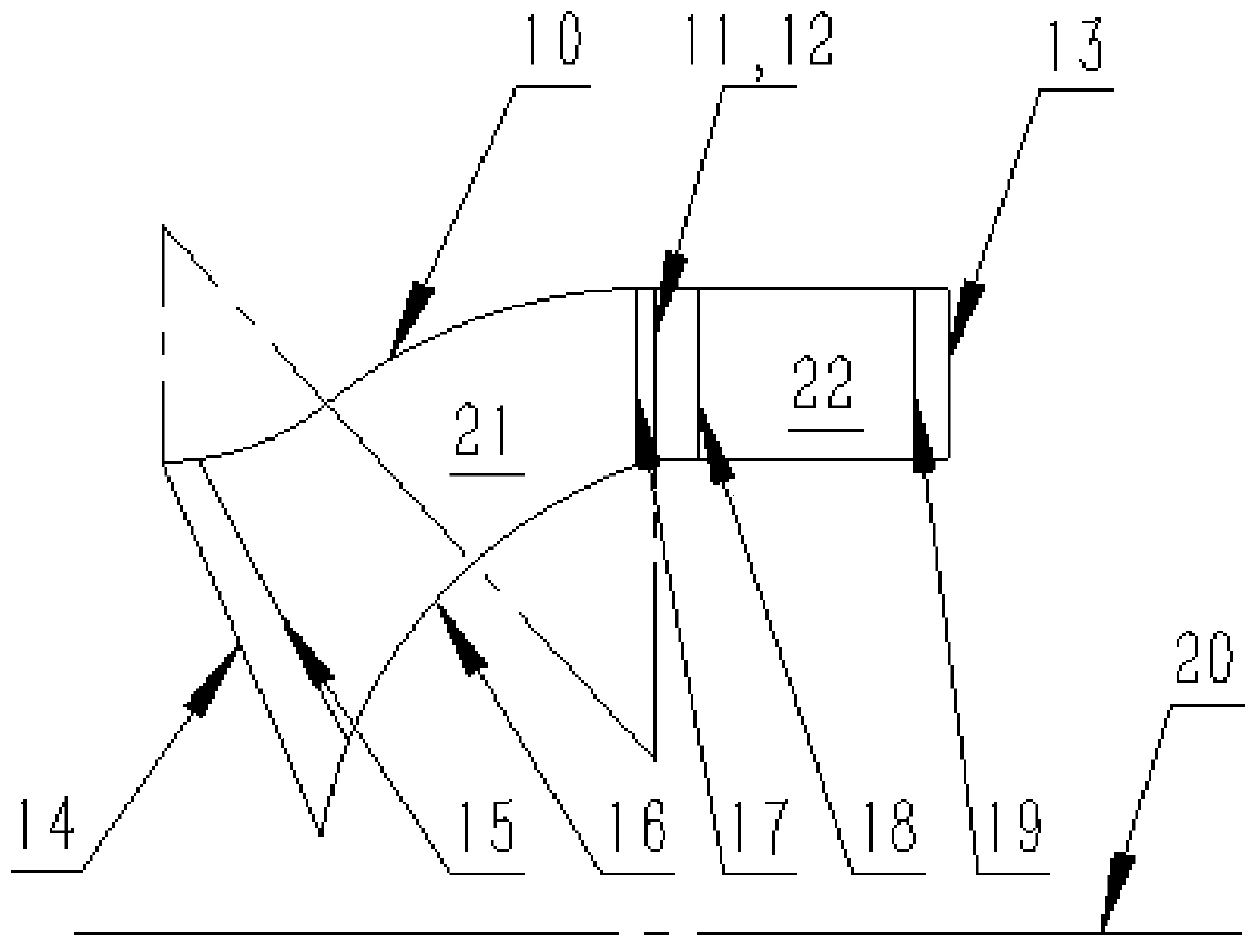
[0033] A number of blades are arranged at equal intervals on the impeller 3, and the blades are arranged along the hub line of the impeller 3; the edges of the blades relative to the hub are two sections of tangent circular arcs with opposite concavity and convexity, and the section close to the collector 1 is a concave secti...


PUM


Abstract

A mixed flow fan comprises a motor, a casing, an impeller, guide vanes and a flow collector. The guide vanes are coaxially and fixedly arranged on the inner side of one end of the casing; the motor isarranged in the center of a hub of the guide vanes; an output shaft of the motor is fixedly connected with the center of the impeller; the flow collector is arranged on the inner side of the other end of the casing, and the flow collector and the impeller are on the same side; the hub of the guide vanes and the hub of the impeller have the same diameter. The variable concave-convex casing line provided by the invention is formed by tangency of a section of concave arc and a section of convex arc, so that the included angle between the inlet and the outlet and the rotating shaft is zero, meanwhile, a large diameter difference between the inlet and the outlet of the impeller can be ensured, and the airflow pressure is increased by fully utilizing centrifugal force. By the adoption of the design, the size of a non-acting area is reduced, airflow axially enters the non-acting area, energy is obtained in the impeller and converted into axial flow from inclined upward flow, then part of kinetic energy of the airflow is converted into pressure energy in the guide vanes, and airflow pressure is improved.

Description

technical field [0001] The invention belongs to the technical field of fans, in particular to a mixed flow fan. Background technique [0002] Mixed flow fans are widely used in mining, textile, metallurgy, power station, aviation, construction and other industries. The mixed flow fan combines the advantages of the axial flow fan and the centrifugal fan, and has a high pressure coefficient and flow coefficient. The air in the mixed-flow fan is both centrifugal and axial. Due to its unique structural characteristics, the interior is full of complex secondary flows. [0003] The mixed flow fan adopts axial air intake, and the flow direction in the impeller changes to an oblique upward flow. After flowing out of the impeller, it needs to be changed to axially enter the rear guide vane or radially enter the volute. The resistance loss is greater when the airflow direction changes. The variable concave-convex meridian channel shape proposed in this patent reduces the flow resis...

Claims


Application Information

Patent Timeline
Patent Type & Authority Applications(China)
IPC IPC(8): F04D25/08F04D23/00F04D29/40F04D29/26F04D29/66
CPCF04D25/08F04D23/00F04D29/403F04D29/26F04D29/666F04D29/667
Inventor 刘小民刘刚
Owner XI AN JIAOTONG UNIV
Why Eureka
Try Eureka