Bridge sling anchorage device pin shaft oiling device and oiling method thereof

A technology of refueling device and anchorage, applied in bridge reinforcement, bridge, bridge maintenance, etc., can solve the problems of lubricating oil consumption, affecting bearing capacity, less oil intake, etc., to improve the lubrication state, increase the service life, reduce the The effect of maintenance and replacement costs

Pending Publication Date: 2019-12-03
无锡金诚工程技术服务有限公司
View PDF0 Cites 2 Cited by
  • Summary
  • Abstract
  • Description
  • Claims
  • Application Information

AI Technical Summary

Problems solved by technology

After opening to traffic, when the car passes the bridge, it will cause the steel box girder of the bridge to vibrate up and down, and cause the pin shaft to rotate slightly in the shaft hole of the fork lug. When the bridge is installed, oil is added between the pin shaft and the shaft hole for lubrication. After a period of time, the lubricating oil in the shaft hole will be exhausted. At this time, the relative rotation between the fork lug and the pin shaft will wear the pin shaft and the shaft hole. Replacing the pin shaft is time-consuming and labor-intensive
[0003] Some bridges try to improve the lubrication state of the pin shaft by adding lubricating oil during maintenance. However, due to the small design clearance between the pin shaft and the shaft hole, the amount of oil introduced by the ordinary refueling method is very small, and the lubricating oil cannot reach the entire bridge. In the middle of the shaft hole, the lubrication problem of the pin shaft cannot be effectively solved
At present, a large number of suspension bridges in China adopt this pin design, and oil lubrication has become a major problem in bridge maintenance.

Method used


Image

  • Bridge sling anchorage device pin shaft oiling device and oiling method thereof
  • Bridge sling anchorage device pin shaft oiling device and oiling method thereof

Examples


Embodiment Construction

[0030] The present invention will be further described in detail below in conjunction with the accompanying drawings and embodiments.

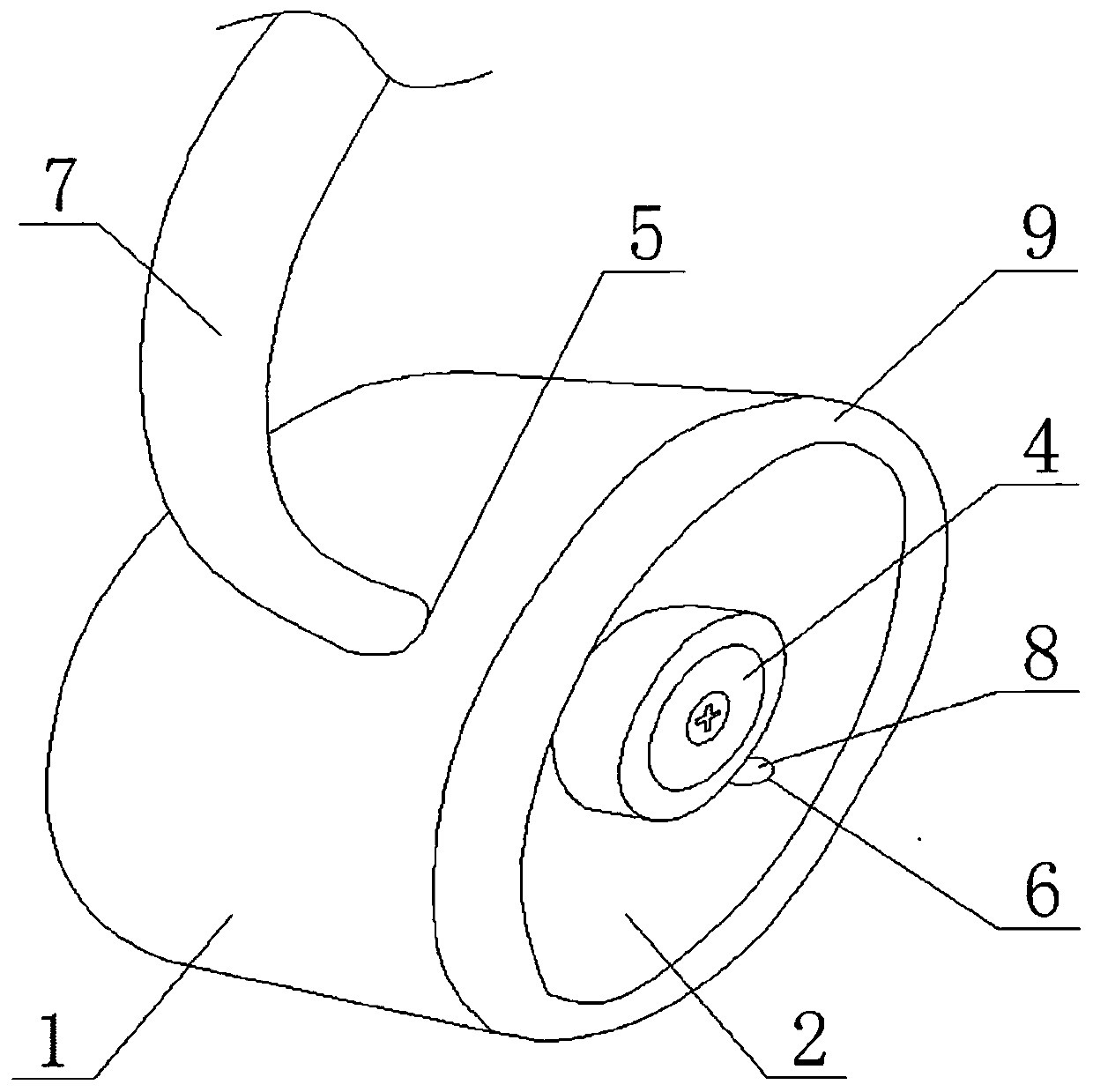
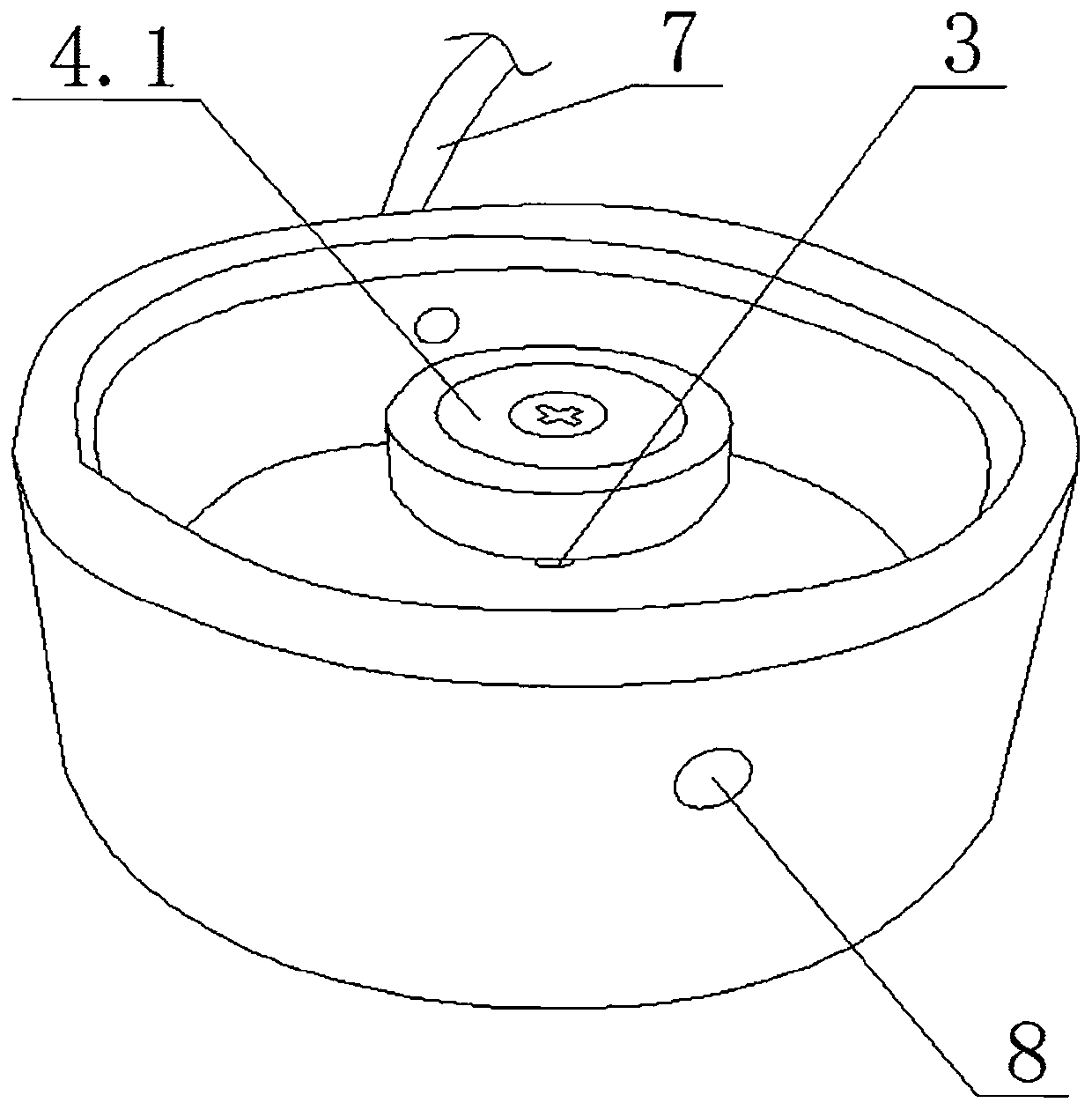
[0031] Such as figure 1 , figure 2 As shown, a bridge sling anchor pin refueling device in this embodiment includes a sealed tank 1, the rear end of the sealed tank 1 closes the front opening, and the open end of the sealed tank 1 is hollowed out to form a circular shape. Oil storage chamber 2, the inner diameter of the circular oil storage chamber 2 is larger than the diameter of the anchor pin shaft, the center of the closed end of the sealed tank 1 is equipped with a fastening bolt 3, and the front end of the fastening bolt 3 passes through the sealed tank 1 to seal The end extends into the circular oil storage chamber 2, the front end of the fastening bolt 3 is provided with a magnetic mechanism 4, the magnetic mechanism 4 includes a permanent magnet 4.1, and a built-in nut is arranged on the rear end surface of the permanent magnet 4.1....


PUM


Abstract

The invention relates to a bridge sling anchorage device pin shaft oiling device and an oiling method thereof. The device comprises a sealing tank (1), the interior of the sealing tank (1) is hollowedout to form a circular oil storage cavity (2), and a fastening bolt (3) is arranged in the center of the closed end of the sealing tank (1) in a penetrating manner; a magnetic mechanism (4) is arranged at the outer end of the fastening bolt and comprises a permanent magnet (4.1), a built-in nut is arranged on the inner end face of the permanent magnet (4.1), and the fastening bolt (3) is connected with the built-in nut; a plastic oil filling pipe (7) and an oil drain valve (8) are arranged on the outer wall of the sealing tank (1), and an annular sealing strip (9) is arranged on the end faceof the opening end of the sealing tank (1). According to the invention, the oil inlet amount of an anchorage device pin shaft can be effectively ensured, and the lubricating oil can reach the middle of a shaft hole, so that the lubricating state of the pin shaft is improved, the service life of the pin shaft is effectively prolonged, and the maintenance and replacement cost of the bridge sling anchorage device pin shaft is reduced.

Description

technical field [0001] The invention relates to a refueling device and a refueling method for a pin shaft of a bridge sling anchor and belongs to the technical field of bridge maintenance. Background technique [0002] The sling of the suspension bridge is connected to the bridge anchor plate through the fork ear and the pin shaft at the lower end of the anchorage, and connects the steel box girder with the main cable, becoming one of the important stress nodes of the bridge superstructure. After opening to traffic, when the car passes the bridge, it will cause the steel box girder of the bridge to vibrate up and down, and cause the pin shaft to rotate slightly in the shaft hole of the fork lug. When the bridge is installed, oil is added between the pin shaft and the shaft hole for lubrication. After a period of time, the lubricating oil in the shaft hole will be exhausted. At this time, the relative rotation between the fork lug and the pin shaft will wear the pin shaft and...

Claims


Application Information

Patent Timeline
Patent Type & Authority Applications(China)
IPC IPC(8): F16N7/00F16N19/00F16N21/04F16N29/02E01D22/00
CPCE01D22/00F16N7/00F16N19/00F16N21/04F16N29/02
Inventor 陈华青薛磊蔡传勇赵敏梁云家向威苏杨熊祖坤李琼星黄贺洪朱迪邬子杰
Owner 无锡金诚工程技术服务有限公司
Why Eureka
Try Eureka