
Oil-free piston type air compressor for new energy vehicle

A technology of new energy vehicles and oil pistons, which is applied in the direction of liquid variable capacity machinery, mechanical equipment, variable capacity pump components, etc., can solve the problems of high maintenance cost, low efficiency, large energy consumption, etc., and improve the service life , Reduce noise, low exhaust temperature

Active Publication Date: 2019-08-09
ZHEJIANG KELI VEHICLE CONTROL SYST
View PDF10 Cites 7 Cited by
  • Summary
  • Abstract
  • Description
  • Claims
  • Application Information

AI Technical Summary

Problems solved by technology

[0003] The present invention aims at the shortcomings of low efficiency, high energy consumption, high use and maintenance cost, and short life in the prior art, and provides an oil-free piston for new energy vehicles with high efficiency, low energy consumption, low use and maintenance cost, and long life. type air compressor

Method used


Image

  • Oil-free piston type air compressor for new energy vehicle
  • Oil-free piston type air compressor for new energy vehicle
  • Oil-free piston type air compressor for new energy vehicle

Examples


Embodiment 1

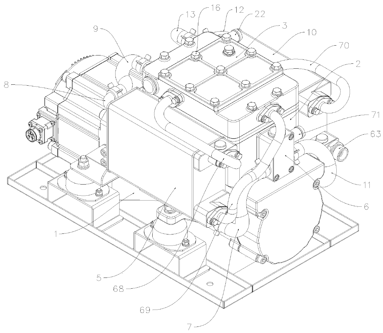
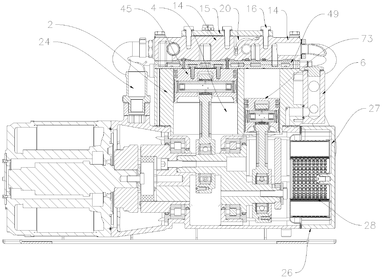
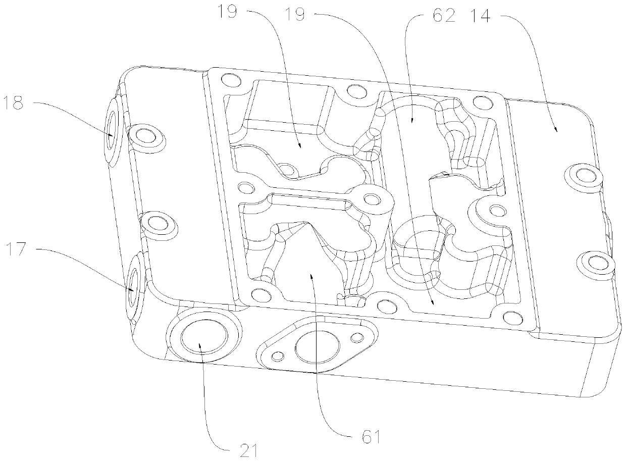
[0043] Oil-free piston air compressors for new energy vehicles, such as Figure 1 to Figure 23As shown, it includes a crankcase 1, a cylinder body 2, and a cylinder head assembly 3. The cylinder body 2 is provided with a piston cylinder 4. The cylinder body 2 is arranged above the crankcase 1 and connected with the crankcase 1. The cylinder head assembly 3 is located on Above the cylinder block 2 and connected with the cylinder block 2, the front side of the cylinder block 2 is provided with a low-pressure heat exchanger 5 connected with the crankcase 1, and the right end of the cylinder block 2 is provided with a manifold block 6 connected with the cylinder block 2, The manifold block 6 and the low-pressure heat exchanger 5 are connected through the first water inlet pipe 7, and the right end of the low-pressure heat exchanger 5 is provided with a first water outlet 8, and the first water outlet 8 is connected with the cylinder head assembly 3 through the first drain pipe 9 T...

Embodiment 2

[0050] Oil-free piston air compressors for new energy vehicles, such as Figure 1 to Figure 23 As shown, on the basis of Embodiment 1, the water channel outer wall 34 and the cylinder outer wall 32 are connected by reinforcing ribs 39, and the reinforcing ribs 39, the water channel outer wall 34, and the cylinder outer wall 32 are enclosed to form a sound-insulating cavity 40, and the sound-insulating cavity 40 is provided with There is a fixed mount 41 connected to the cylinder body 2, the lower end of the fixed mount 41 is flush with the lower end of the soundproof cavity 40, and the upper end of the fixed mount 41 is located in the soundproof cavity 40. The fixed mount 41 includes a cylinder 42 and a cylindrical body The connecting rib 43 connected to the periphery of the body 42, the cylindrical body 42 is connected with the cylinder body 2 through the connecting rib 43, and the middle part of the cylindrical body 42 is provided with an installation through hole 44. A soun...

Embodiment 3

[0052] Oil-free piston air compressors for new energy vehicles, such as Figure 1 to Figure 23 As shown, on the basis of Embodiment 2, the upper end of the crankcase 1 is provided with a bar-shaped air inlet 23 arranged from front to back, and the top of the bar-shaped air inlet 23 is provided with an air inlet joint 24 connected with the crankcase 1, Both sides of the upper end of the crankcase 1 are provided with two air intake passages 25 arranged in parallel, the air intake passages 25 are arranged horizontally from left to right, the left end of the air intake passage 25 communicates with the strip air inlet 23, and the right side of the crankcase 1 An air filter assembly 26 connected to the crankcase 1 is arranged on the side, and the air filter assembly 26 includes an air filter housing 27 and an air filter element 28 arranged in the inner cavity of the air filter housing 27. The air filter air inlet 29 communicated with the right end of the air intake passage 25, the a...


PUM


Abstract

The invention relates to the technical field of air compressors, and discloses an oil-free piston type air compressor for a new energy vehicle. The oil-free piston type air compressor for the new energy vehicle comprises a crank case, a cylinder body and a cylinder head assembly, wherein a piston cylinder is arranged in the cylinder body; the cylinder body is arranged above the crank case and is connected with the crank case; the cylinder head assembly is arranged above the cylinder body and is connected with the cylinder body; a low-pressure heat exchanger connected with the crank case is arranged on the front side of the cylinder body; a manifold block connected with the cylinder body is arranged at the right end of the cylinder body and is connected with the low-pressure heat exchangerthrough a first water inlet pipe; a first water outlet is formed in the left end of the low-pressure heat exchanger and is connected with the cylinder head assembly through a first drainage pipe; a high-pressure heat exchanger connected with the crank case is arranged on the back side of the cylinder body; the manifold block and the high-pressure heat exchanger are connected through a second waterinlet pipe; and a second water outlet is formed in the left end of the high-pressure heat exchanger and is connected with the cylinder head assembly through a second drainage pipe. The oil-free piston type air compressor for the new energy vehicle provided by the invention adopts water-cooling and air-cooling double-acting cooling manners so as to be sufficient in cooling and better in effect.

Description

technical field [0001] The invention relates to the technical field of air compressors, in particular to an oil-free piston air compressor for new energy vehicles. Background technique [0002] Oil-free piston air compressors for new energy vehicles mainly include crankcases, cylinder blocks, cylinder heads, motors, crankshafts, connecting rods, pistons, cooling fans and other components. Most of the current oil-free piston air compressors use single-stage compression method, this single-stage compression method has high energy consumption and low gas pressure; in addition, these oil-free piston air compressors currently use fan forced air cooling to dissipate heat, which mainly relies on convection conduction to dissipate heat. The thermal efficiency is also low. The heat of the air compressor cylinder block, cylinder head, especially the internal moving parts such as connecting rods and pistons accumulates for a long time, and the temperature cannot be quickly and effectiv...

Claims


Application Information

Patent Timeline
Patent Type & Authority Applications(China)
IPC IPC(8): F04B25/00F04B39/06F04B39/10F04B39/12F04B39/16F04B39/00
CPCF04B25/005F04B39/0005F04B39/0027F04B39/0094F04B39/06F04B39/102F04B39/122F04B39/123F04B39/125F04B39/128F04B39/16
Inventor 邬泽强王少鹏方优正章胡杰
Owner ZHEJIANG KELI VEHICLE CONTROL SYST
Learn More