
Thermal power plant boiler capable of controlling waste residue discharge

A technology for thermal power plants and boilers, applied in the field of boilers in thermal power plants, can solve problems such as blockage of the discharge port, affecting the normal use of the boiler, affecting the combustion of fuel, etc., to achieve the effect of boiler stability

Inactive Publication Date: 2019-12-03
XIAN LANXIN IND AUTOMATION ENG CO LTD
View PDF0 Cites 0 Cited by
  • Summary
  • Abstract
  • Description
  • Claims
  • Application Information

AI Technical Summary

Problems solved by technology

[0003] A thermal power plant is referred to as a thermal power plant. It is a factory that uses coal, oil, and natural gas as fuel to produce electric energy. Set the relevant control equipment, thereby affecting the combustion of fuel
Moreover, the outlet of the boiler in the existing power plant is prone to blockage, which affects the normal use of the boiler.
[0004] For the problems in related technologies, no effective solutions have been proposed yet

Method used


Image

  • Thermal power plant boiler capable of controlling waste residue discharge
  • Thermal power plant boiler capable of controlling waste residue discharge

Examples


Embodiment 1

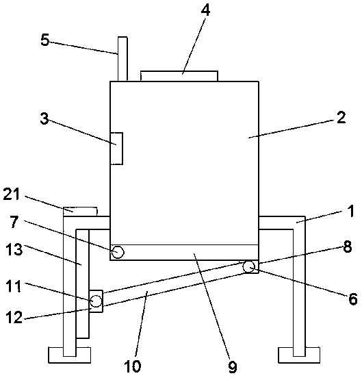
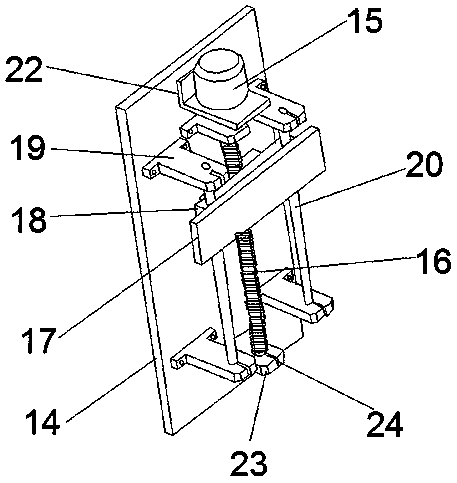
[0022] see Figure 1-2 According to an embodiment of the present invention, a thermal power plant boiler capable of controlling waste slag discharge includes a support frame 1 on which a boiler 2 is fixed, and the support frame 1 supports the boiler 2 as a whole function, the boiler 2 is fixed with an infrared sensor 3, through which the infrared sensor 3 is installed to sense and detect the position of the waste slag in the boiler 2, and the top of the boiler 2 is provided with a feed port 4, through the feed port 4, to the Fuel is put into the boiler 2, and an exhaust pipe 5 is fixedly connected to one side of the feed port 4, and gas is discharged through the exhaust pipe 5. The bottom of the boiler 2 is provided with a baffle 9, and through the baffle 9, the The waste slag plays a supporting role, and the baffle plate 9 is connected with the boiler 2 through the movable shaft-7, and is movably connected by being provided with the movable shaft-7, so as to facilitate the op...

Embodiment 2

[0024] see Figure 1-2 , for the support frame 1, the support frame 1 is fixed with a controller 21, the controller 21 is electrically connected with the infrared sensor 3 and the motor 15, and the controller 21 is connected to the The infrared sensor 3 is electrically connected with the motor 15. When the infrared sensor 3 senses that the amount of waste residue increases, a signal will be sent to the controller 21, and the controller 21 will control the motor 15 to work, so that the waste residue can be discharged in time. As for the fixing plate 14 , a motor base 22 is fixed on the fixing plate 14 , the motor 15 is fixed on the motor base 22 , and the motor 15 is fixed by the motor base 22 . As for the fixing plate 14 , the second supporting plate 23 is symmetrically arranged on the fixing plate 14 , and the screw 16 penetrates through the second supporting plate 23 . For the support plate one 19, the tops of the support plate one 19 and the support plate two 23 are provid...


PUM


Abstract

The invention discloses a thermal power plant boiler capable of controlling waste residue discharge. The boiler comprises a support frame; a boiler is fixedly arranged on the support frame; an infrared sensor is fixedly arranged in the boiler; a feeding hole is formed in the top of the boiler; an exhaust pipe is fixedly connected to one side of the feeding hole; a baffle is arranged at the bottomof the boiler; the baffle is connected with the boiler through a movable shaft I; a fixed block is arranged on one side of the baffle; a movable shaft II is arranged on the fixed block; the movable shaft II is sleeved in a movable column, the end, away from the movable shaft II, of the movable column is fixed to a movable block through a movable shaft III, a moving mechanism is arranged on one side of the support frame, the moving mechanism comprises a fixing plate, the fixing plate is fixed to one side of the support frame, and a motor is fixedly arranged on the fixing plate. The boiler has the beneficial effects that the boiler can rapidly complete waste residue discharging, and the situation that normal work of the boiler is affected due to blockage of the discharging port is avoided.

Description

technical field [0001] The invention relates to the technical field of thermal power plant control, in particular to a thermal power plant boiler capable of controlling waste slag discharge. Background technique [0002] The boiler is a kind of energy conversion equipment. The energy input to the boiler includes chemical energy and electric energy in the fuel, and the boiler outputs steam, high-temperature water or organic heat carrier with a certain amount of heat energy. The original meaning of the pot refers to the water container heated on the fire, and the furnace refers to the place where fuel is burned. The boiler includes two parts: the pot and the furnace. The hot water or steam generated in the boiler can directly provide the required heat energy for industrial production and people's life, and can also be converted into mechanical energy through a steam power device, or converted into electrical energy through a generator. [0003] A thermal power plant is referr...

Claims


Application Information

Patent Timeline
IPC IPC(8): F23J1/00
CPCF23J1/00F23J2900/01009
Inventor 王岚
Owner XIAN LANXIN IND AUTOMATION ENG CO LTD
Learn More