Reference hole arrangement method

A datum hole and measurement datum technology, applied in aircraft assembly, measuring devices, instruments, etc., can solve the problems of inability to accurately reflect the assembly state of parts and high measurement complexity, reduce the measurement complexity, improve the hole position accuracy, The effect of reducing the number of

Active Publication Date: 2019-12-03
CHENGDU AIRCRAFT INDUSTRY GROUP
View PDF8 Cites 9 Cited by
  • Summary
  • Abstract
  • Description
  • Claims
  • Application Information

AI Technical Summary

Problems solved by technology

[0007] In view of the shortcomings that the existing reference hole arrangement method cannot accurately reflect the assembly state of the part or the measurement complexity is high, a general reference hole arrangement method based on the deformation of the part is proposed

Method used


Image

  • Reference hole arrangement method
  • Reference hole arrangement method
  • Reference hole arrangement method

Examples


Embodiment 1

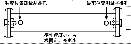
[0027] Such as figure 1 As shown, when the measured maximum deformation of the part is , the hole position error assigned to the hole position correction link through the tolerance is , then when the deformation of the part is small, satisfying When , it is considered that the hole position accuracy at the position with the largest deformation can still meet the hole-making requirements. At this time, the influence of the deformation of the part itself on the hole-making hole position accuracy is not considered, and only the influence of the assembly position of the part on the hole-making hole position accuracy is considered. Therefore, it is only necessary to arrange datum holes at both ends of the part.

Embodiment 2

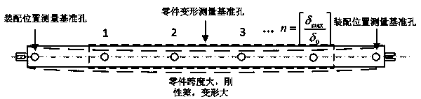
[0029] When the deformation of the part is large and meets the requirement, if the deformation of the part is large in the local area of ​​the part, if the influence of the deformation of the part is not considered, the hole position made by automatic hole making will not meet the hole position accuracy requirements. At this time, it is first necessary to arrange reference holes at both ends of the part to measure the assembly position of the part, and secondly arrange reference holes between the reference holes at both ends for measuring the deformation of the part, the number of which is:

[0030] ;[] stands for rounding

[0031] After this arrangement, no need to consider the deformation of the part between any two deformation reference holes, it can also meet the accuracy requirements of the hole making hole, and achieve the purpose of using a small number of reference holes to reflect the assembly deformation of the part, such as figure 2 shown.

Embodiment 3

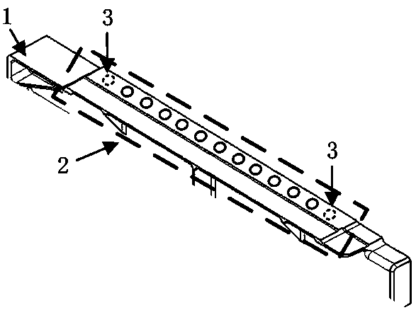
[0033] Such as image 3 As shown, in a digital assembly system, a laser tracker is used to measure the position of the reference hole. The product requires the accuracy of the hole position to be ±0.6mm, of which the accuracy of the reference hole itself is ±0.2mm, the measurement accuracy of the laser tracker is ±0.05mm, and the accuracy assigned to the hole position correction link is ±0.35mm . After using the laser tracker to sample and fit the part shape at multiple points, the maximum deformation of a certain upper girder is 0.2mm, and the maximum deformation of a certain sheet metal frame is 0.9mm.

[0034] For the upper girder, due to , it is only necessary to arrange the assembly position measurement reference holes at both ends of the part.


PUM


Abstract

The invention discloses a reference hole arrangement method. The method comprises the steps of (S1) measuring the deformation of an assembled segment-mounted part through a measuring instrument, (S2)dividing reference holes into two types which comprises (1) part assembly position measurement reference holes for feeding back an actual assembly position of a part and (2) part deformation measurement reference holes for feeding back the deformation condition of the part, and (S3) arranging the reference holes in the part according to an error allocated to a hole site correction link, wherein ahole error distributed to the hole site correction link through tolerance is delta 0 when measured part maximum deformation is delta max, the reference holes are only arranged in two ends of the partwhen the deformation of the part is small and a condition (delta max) / (delta 0) is smaller than 1 is satisfied, the reference holes are arranged in the two ends of the part when a condition (delta max) / (delta 0) is larger than or equal to 1 is satisfied, and the reference holes for measuring the deformation of the part are arranged between the reference holes in the two ends. The reference hole arrangement method has the advantages that the actual assembly condition of the part can be accurately reflected to an automatic drilling system, the drilling hole position precision is improved, that corrected drilling hole positions meet a precision requirement is guaranteed, meanwhile, the number of the reference holes can be effectively reduced, the reference hole measurement complexity is reduced, and the production efficiency is improved.

Description

technical field [0001] The invention relates to a new method for arranging reference holes on parts for correcting automatic hole positions in the process of automatic hole making. Background technique [0002] In order to meet the high-quality and high-efficiency hole-making requirements of modern aircraft, automatic hole-making technology has been gradually applied in the assembly of aircraft skin panels and aircraft components. Because there are errors in the manufacturing, positioning and assembly of aircraft structural parts, there is often a certain deviation between the assembled product and the theoretical digital model. At this time, if the automatic hole making system directly makes holes according to the theoretical hole positions, actual holes will inevitably appear. There is a large deviation between the hole position and the theoretical hole position, so the actual hole position needs to be corrected. The measurement system before automatic hole making compare...

Claims


Application Information

Patent Timeline
IPC IPC(8): G01B21/32B64F5/10
CPCB64F5/10G01B21/32
Inventor 付建超何凤涛樊西锋张在学谭明维彭志军薛松郭喜锋谢明伟
Owner CHENGDU AIRCRAFT INDUSTRY GROUP
Why Eureka
Try Eureka