
Rapid calculation method for realizing tight focusing of partially coherent light

A fast calculation and tight focusing technology, applied in optics, optical components, instruments, etc., can solve the problems of restricting the research of tight focusing characteristics, increasing calculation time, and consuming calculation time, so as to shorten calculation time, reduce distortion, and reduce calculation. Distortion effect

Active Publication Date: 2019-12-03
SUZHOU UNIV
View PDF4 Cites 10 Cited by
  • Summary
  • Abstract
  • Description
  • Claims
  • Application Information

AI Technical Summary

Problems solved by technology

For the case of partially coherent light field as the incident field, the double integral in the vector diffraction integral formula is extended to the quadruple integral, and the calculation time is greatly increased
For example, when calculating the tightly focused focal field distribution of multi-Gaussian Shell mode correlated beams, it takes about 60 hours of calculation time to obtain 50 by 50 data points directly integrated by the commercial software Mathematica, and when the coherence of the initial incident partially coherent beam is relatively low When the value is low, the result calculated by the vector diffraction integral formula is severely distorted
Therefore, it greatly limits the study of tight focusing characteristics in the case of partial coherence
[0006] At present, in the existing technology of calculating light tight focusing process, in 2006 Leutenegger et al. proposed to use fast Fourier transform method to replace the vector diffraction integral formula proposed by Richards and Wolf. Although the time-consuming technology is very short, it is only applicable to The case where the incident beam is fully coherent, but not valid for partially coherent light

Method used


Image

  • Rapid calculation method for realizing tight focusing of partially coherent light
  • Rapid calculation method for realizing tight focusing of partially coherent light
  • Rapid calculation method for realizing tight focusing of partially coherent light

Examples


Embodiment Construction

[0024] The present invention will be further described below in conjunction with the accompanying drawings and specific embodiments, so that those skilled in the art can better understand the present invention and implement it, but the examples given are not intended to limit the present invention.

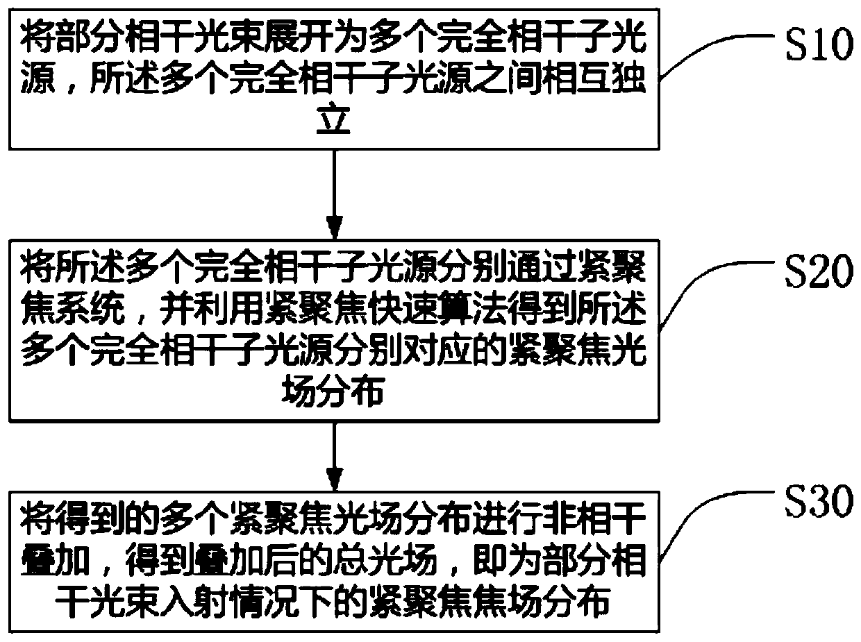
[0025] The fast calculation method for realizing the tight focusing of partially coherent light in this embodiment includes the following steps:

[0026] S10. Expand the partially coherent light beam into multiple fully coherent sub-light sources, and the multiple fully coherent sub-light sources are independent of each other;

[0027] Among them, when the incident beam in the tightly focused system is a partially coherent beam, its second-order statistical properties can be expressed by the following coherence matrix:

[0028] W(r 1 , r 2 )=* (r 1 )E T (r 2 )>, (1)

[0029] Among them, E(r) represents the random electric field at point r in space, * represents the complex c...


PUM


Abstract

The invention discloses a rapid calculation method for realizing tight focusing of partially coherent light. The method comprises the following steps: S10, enabling one part of coherent light beam tobe expanded into a plurality of completely coherent sub light sources and enabling the plurality of completely coherent sub light sources to be independent from each other; S20, enabling the pluralityof completely coherent sub light sources to respectively pass through a tight focusing system and acquiring tight focusing light field distribution respectively corresponding to the plurality of completely coherent sub light sources by utilizing a tight focusing fast algorithm; S30, carrying out incoherent superposition on the obtained distribution of the plurality of tightly focused light fieldsto obtain a superposed total light field so as to obtain tightly focused focal field distribution under the partially coherent light beam incident condition. According to the disclosed method, the quadruple integral form of a vector diffraction integral formula under the condition of partial coherent light incidence is changed into a fast Fourier transform and summation form, so that the calculation time is shortened, the calculation efficiency is improved, and the tight focusing calculation precision under the condition of partial coherence is greatly improved; and the distortion in the calculation process is also reduced.

Description

technical field [0001] The invention relates to the field of tight focusing calculation of light beams, in particular to a fast calculation method for realizing tight focusing of partially coherent light. Background technique [0002] When a beam of light is focused by an optical high numerical aperture, the traditional paraxial beam transmission theory is no longer applicable. This is because when the light is focused through the optical high numerical aperture, the wave vector of the light will be deflected at a large angle toward the focal point of the numerical aperture, so that the initial light field containing only the electric field components in the x and y directions becomes A 3D distributed light field with x, y and z components. Therefore, it is necessary to use non-paraxial transmission theory to deal with the problem of beam focusing through optical high numerical aperture. The above problem of focusing a beam through an optical high numerical aperture is usu...

Claims


Application Information

Patent Timeline
Patent Type & Authority Applications(China)
IPC IPC(8): G02B27/42G02B27/00
CPCG02B27/0012G02B27/4266
Inventor 童瑞寰陈亚红王飞蔡阳健
Owner SUZHOU UNIV
Learn More