Toner cartridge

A toner cartridge and toner technology, used in electrographics, optics, instruments, etc., can solve problems such as poor printing, uneven powder application, and complexity, and achieve stable printing quality, fewer parts, and fewer assembly processes. Effect

Pending Publication Date: 2019-12-03
PRINT RITE UNICORN IMAGE PROD CO LTD OF ZHUHAI
View PDF0 Cites 0 Cited by
  • Summary
  • Abstract
  • Description
  • Claims
  • Application Information

AI Technical Summary

Problems solved by technology

Since the conductive parts are separated from each other and connected to the developing components respectively, the conductive end of the toner cartridge 1 has many components and has a complex structure, so that there are many procedures during assembly, and the cost of the toner cartridge 1 is relatively high.
Moreover, a plurality of conductive contacts that are separated from each other may cause the uneven voltage receiving the imaging device, causing the carbon powder on the toner cartridge 1 to be powdered unevenly when it is transferred from the powder chamber to the developing roller 12 and the photosensitive drum, thereby cause poor printing

Method used


Image

  • Toner cartridge
  • Toner cartridge
  • Toner cartridge

Examples


no. 1 example

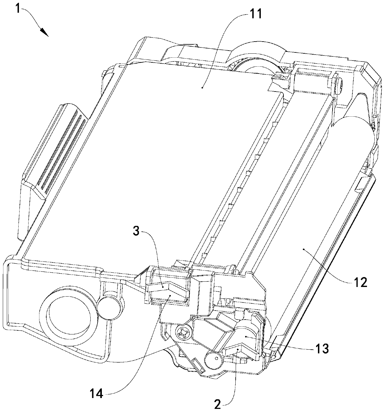
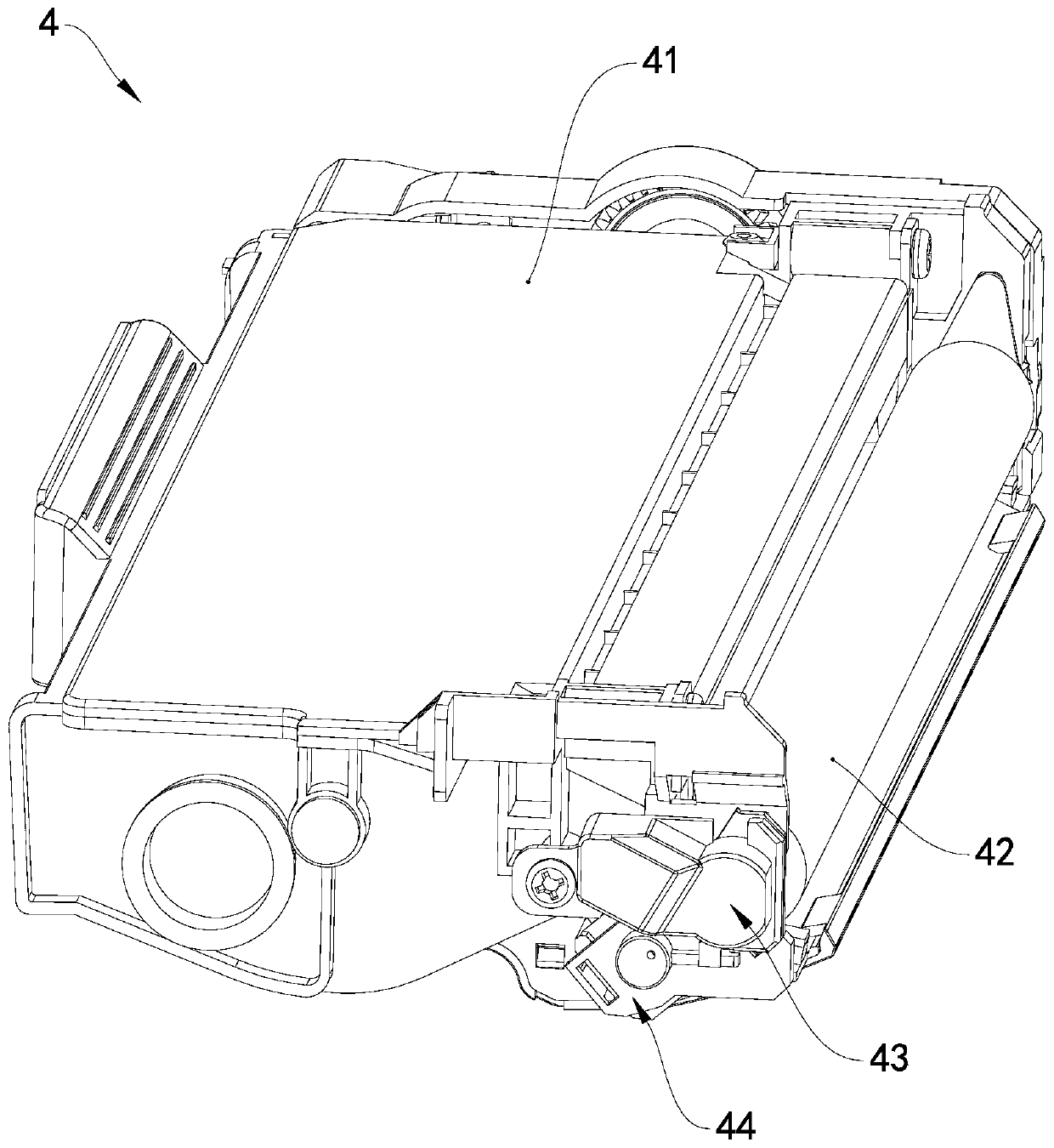
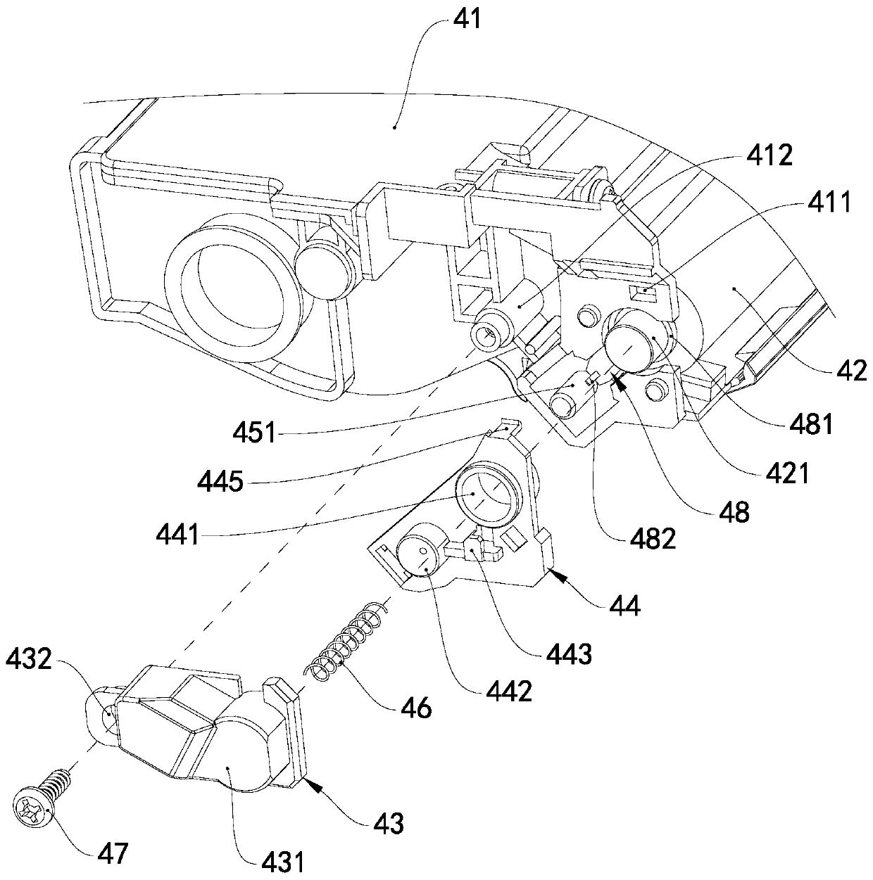
[0032] see figure 2 and image 3 , the toner cartridge 4 includes a box body 41, a developing roller 42, a powder feeding roller, a conductive plastic part 43, a metal part 48 and a bearing 44, the box body 41 has a toner cavity for accommodating carbon powder, the conductive plastic part 43 and the metal part 48 Located outside the same end wall of the box body 41 . The developing roller 42 is rotatably supported between the two end walls of the box body 41 , and the developing roller 42 includes a developing roller shaft 421 supported on the two end walls of the box body 41 . The powder feeding roller is rotatably supported between the two end walls of the box body 41 , and the powder feeding roller includes a powder feeding roller shaft 451 supported on the two end walls of the box body 41 .

[0033] see Figure 4 , the conductive plastic part 43 has an electrical contact portion 431 and an output portion 433 , the electrical contact portion 431 is used to contact an ou...

no. 2 example

[0039] As an explanation of the second embodiment of the toner cartridge of the present invention, only the differences from the first embodiment of the toner cartridge will be described below.

[0040] see Figure 10 and Figure 11 , the toner cartridge 5 includes a box body 51, a developing roller 52, a powder feeding roller, a conductive plastic part 53, a metal part 55 and an end cover 54, and the conductive plastic part 53 has an electrical contact contact part 532 and an output part 533, and the electrical contact The contact part 532 is used to contact with an output electrical contact of the imaging device, and the output part 533 is in contact with one end of the powder feeding roller shaft 561 . The end cover 54 is installed on one end wall of the box body 51 , and the output part 533 is located between the end cover 54 and the box body 51 .

[0041] see Figure 12 , the conductive plastic part 53 also has a main body 531 , and the electrical contact portion 532 a...


PUM


Abstract

The invention provides a toner cartridge. The toner cartridge comprises a body having a toner cavity for accommodating the toner, a developing roller which can be supported between two end walls of the box body in a manner of rotating around the axis of the developing roller and comprises a developing roller shaft supported on the two end walls of the box body, a toner feeding roller which can besupported between the two end walls of the box body in a manner of rotating around the axis of the toner feeding roller and comprises a toner feeding roller shaft supported on the two end walls of thebox body, a conductive plastic part, and a metal member, wherein the conductive plastic part has an electric contact point contact part and an output part, the electric contact point contact part isused for being in contact with an output electric contact point of imaging equipment, the output part is in contact with one end of the developing roller shaft / one end of the toner feeding roller shaft, two ends of the metal member are respectively in contact with the developing roller shaft and the toner feeding roller shaft, and the conductive plastic part and the metal member are arranged at an outer side of the same end wall of the body. The toner is stably transferred from the toner feeding roller to the developing roller, so the toner is more uniformly fed into the toner cartridge, andthe printing quality is stable. The toner cartridge has advantages of few parts, simple structure, few assembly procedures and lower cost.

Description

technical field [0001] The invention relates to the technical field of printing consumables, in particular to a toner cartridge detachably installed in an imaging device. Background technique [0002] Electrophotographic imaging equipment, such as laser printers, is a device that uses the principle of electrophotography to form an image on an image forming medium such as paper through processes such as charging, exposure, development, transfer, fixing, and cleaning. Imaging devices typically provide toner using a toner cartridge that is removably mounted therein. In addition to containing carbon powder, the toner cartridge is usually integrated with developing components such as a developing roller, a powder feeding roller, and a powder outlet knife. The thickness of the toner layer on the developing roller is adjusted, and the developing roller uses the toner carried on it to develop the electrostatic latent image on the photosensitive element. During the development proc...

Claims


Application Information

Patent Timeline
IPC IPC(8): G03G15/08
CPCG03G15/0865G03G15/0877
Inventor 杨晓锋苏健强
Owner PRINT RITE UNICORN IMAGE PROD CO LTD OF ZHUHAI
Why Eureka
Try Eureka