
Switch coding device for electric appliance

A technology of switch coding and electrical appliances, which is applied in the direction of electric switches, electronic switches, circuits, etc., and can solve problems such as complex structures and water leakage

Pending Publication Date: 2019-12-03
中山市擎宇创业电子科技有限公司
View PDF0 Cites 0 Cited by
  • Summary
  • Abstract
  • Description
  • Claims
  • Application Information

AI Technical Summary

Problems solved by technology

Existing problems are: the structure is complex, holes need to be opened on the electrical panel, and there is a hidden danger of water leakage

Method used


Image

  • Switch coding device for electric appliance
  • Switch coding device for electric appliance
  • Switch coding device for electric appliance

Examples


Embodiment 1

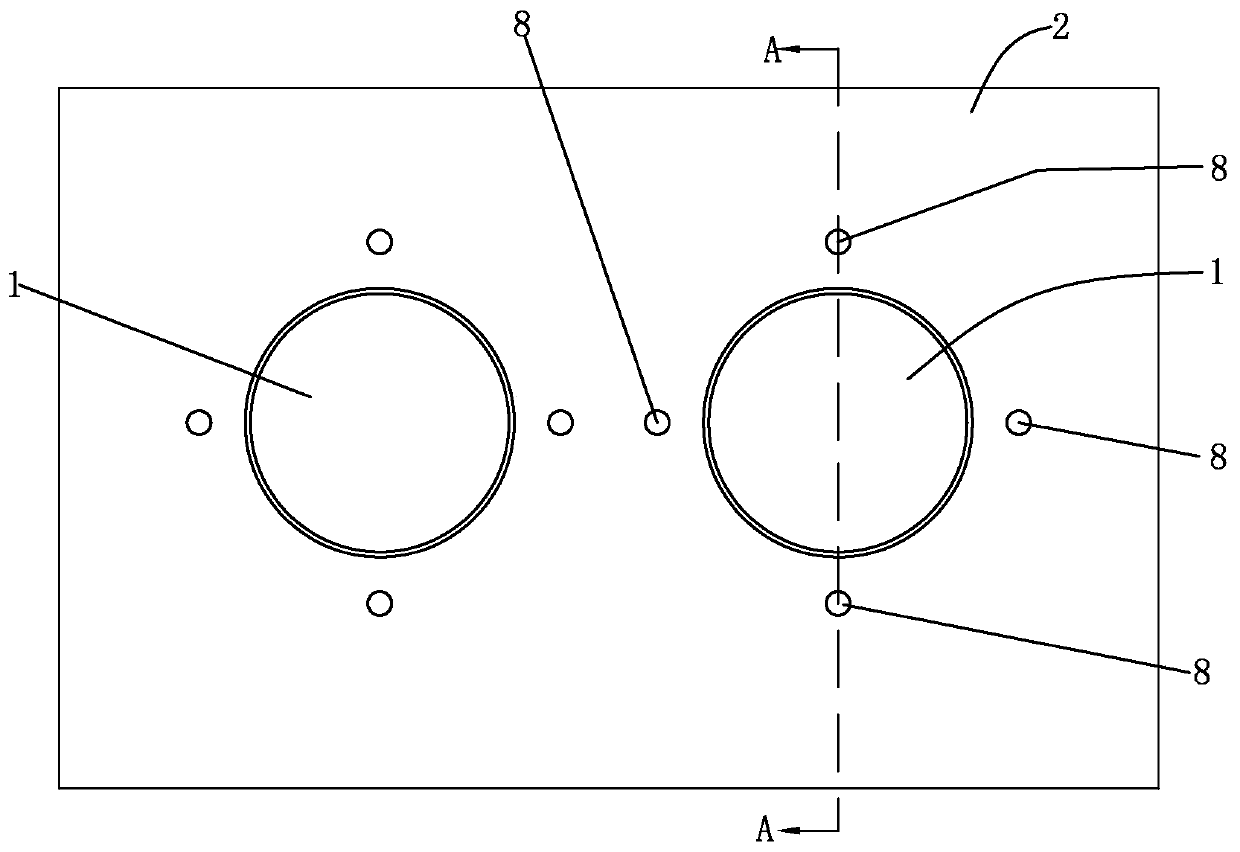
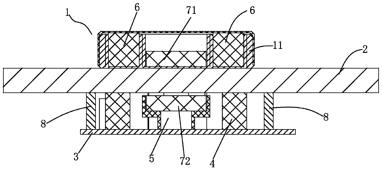
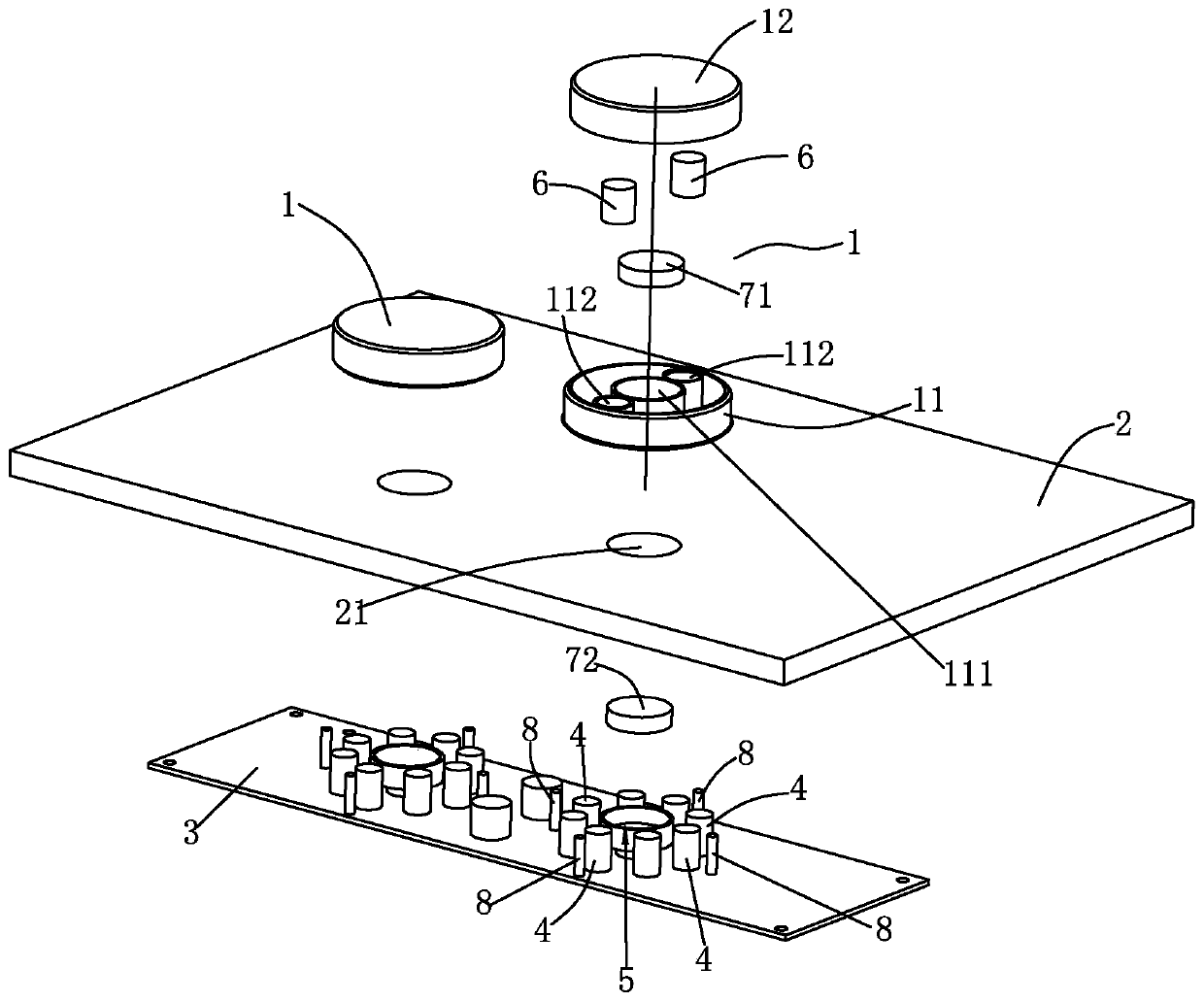
[0020] Such as figure 1 , figure 2 As shown, a switch encoding device for electrical appliances includes a knob 1, an electrical panel 2 made of non-magnetic material, a circuit board 3 and a signal generating part 4 arranged on the circuit board; the signal generating part 4 is a touch Buttons, the touch buttons are distributed in a circle on the circuit board 3;

[0021] Also comprises the magnet base 5 that is located on the circuit board 3, the column body 6 that conductive material is made, moving magnet 71 and static magnet 72,

[0022] The moving magnet 71 is arranged at the center of the knob 1, and the cylinder 6 made of conductive material is arranged on the radial direction of the knob 1; the moving magnet 72 is arranged in the magnet seat 5; Fitting with the electrical panel 3, the knob 1 is rotated, and the cylinder 6 made of conductive material cooperates with different touch buttons;

[0023] The knob 1 includes a bottom case 11 and a top cover 12, the botto...

Embodiment 2

[0027] There is one cylinder 6 made of conductive material, and when the knob 1 is rotated, the cylinder 6 cooperates with different touch keys in different phases.

Embodiment 3

[0029] There are two cylinders 6 made of the conductive material and they are on a diameter line relative to the left and right directions of the electrical panel 2 .

[0030] In an embodiment, the electrical panel 3 is provided with functional icons 22 opposite to the signal generating part 4, one functional icon 22 is provided with a plus sign indicator, and the other functional icon 22 is provided with a minus sign indicator; 1 When it is removed from the electrical panel 3, the two touch buttons located on the straight line in the left and right direction among the touch buttons correspond to the plus sign icon and the minus sign icon respectively; touching the plus sign indicator is equivalent to turning knob 1 clockwise Turn and touch the minus sign, which is equivalent to turning knob 1 counterclockwise.


PUM


Abstract

A switch coding device for an electric appliance comprises a knob, an electric appliance panel made of a non-magnetic material, a circuit board and a signal generating component arranged on the circuit board. The signal generating component is touch keys, and the touch keys are circularly distributed on the circuit board. The device further comprises a magnet seat arranged on the circuit board, acolumn body made of a conductive material, a movable magnet and a static magnet, wherein the movable magnet is arranged in the center of the knob; the column body made of the conductive material is arranged in the radial direction of the knob; the moving magnet is arranged in the magnet seat; the moving magnet and the static magnet are attracted; the touch key is attached to the electric appliancepanel; and the knob rotates, and the column body made of the conductive material matched with the touch key. Due to the adoption of the structure, a hole does not need to be formed in the panel, andthe hidden danger of water leakage is eliminated; a rotating shaft and a rotating disc are omitted, and the structure is simple.

Description

technical field [0001] The invention relates to a switching device. Background technique [0002] In the prior art, a switch encoding device for electrical appliances includes a knob, a drive shaft, a rotating disc, an electrical panel made of non-magnetic material, a circuit board and a Hall sensor on the circuit board. Existing problems are: the structure is complicated, holes need to be drilled on the electrical panel, and there is a hidden danger of water leakage. Contents of the invention [0003] The object of the present invention is to provide a switch coding device for electrical appliances, which has the characteristics of simple structure, no interference from magnetic field, and elimination of hidden danger of water leakage. [0004] The present invention is achieved in this way: a switch encoding device for electrical appliances, including a knob, an electrical panel made of non-magnetic material, a circuit board, and a signal generating component arranged on...

Claims


Application Information

Patent Timeline
IPC IPC(8): H01H19/54H03K17/97
CPCH01H19/54H03K17/97
Inventor 贾永福邹平原伍亚雄
Owner 中山市擎宇创业电子科技有限公司
Learn More