Transmission shaft straightening machine

A transmission shaft and straightening machine technology, applied in the direction of feeding device, positioning device, storage device, etc., can solve the problems affecting the production accuracy and quality of products, the inability to effectively ensure the accuracy of the transmission shaft, and increase the difficulty of straightening and processing the transmission shaft Issues such as sex and complexity

Pending Publication Date: 2019-12-06
ZHEJIANG FOERTAI INTELLIGENT EQUIP CO LTD
View PDF0 Cites 14 Cited by
  • Summary
  • Abstract
  • Description
  • Claims
  • Application Information

AI Technical Summary

Problems solved by technology

[0002] Automobile transmission shafts generally need to be inspected and straightened during subsequent processing to ensure the accuracy and stability of the production and use of the transmission shaft; however, the straightening processing of conventional transmission shafts generally uses the clamping cylinder on the machine tool to clamp the transmission shaft Hold and fix the transmission shaft manually by the user, such as stamping and hammering. This alignment method not only increases the difficulty and complexity of the straightening process of the transmission shaft by the manufacturer, but also cannot effectively guarantee the transmission shaft. The accuracy of shaft alignment greatly affects the production accuracy and quality of subsequent transmission shaft processing products

Method used


Image

  • Transmission shaft straightening machine
  • Transmission shaft straightening machine
  • Transmission shaft straightening machine

Examples


Embodiment Construction

[0020] The preferred embodiments of the present invention will be described in detail below in conjunction with the accompanying drawings, so that the advantages and features of the present invention can be more easily understood by those skilled in the art, so as to define the protection scope of the present invention more clearly.

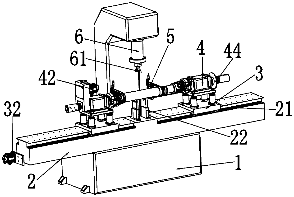
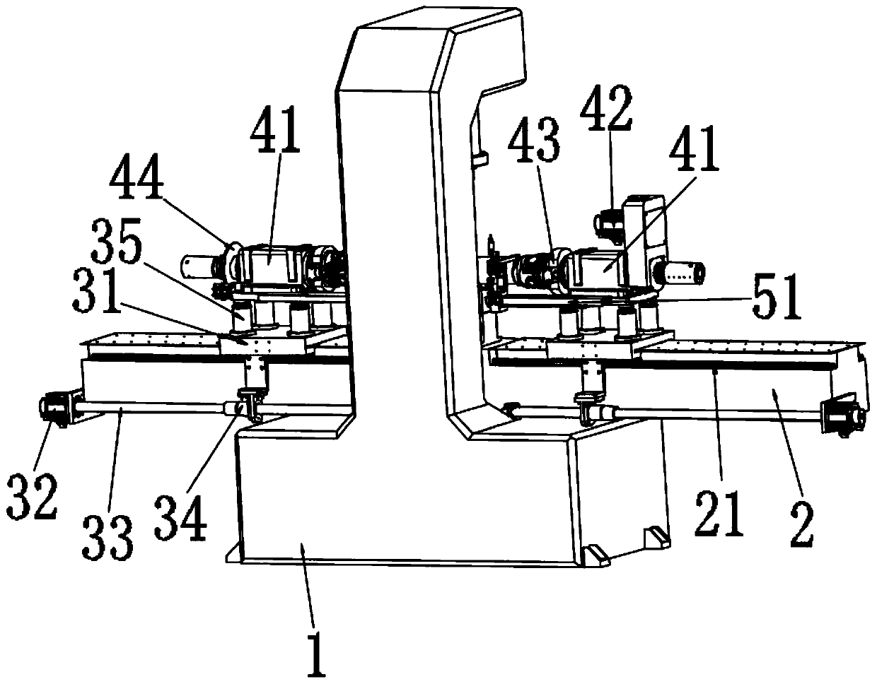
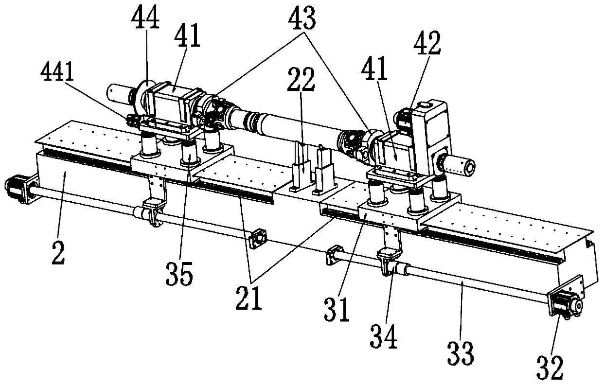
[0021] Such as Figure 1 to Figure 4 A transmission shaft straightening machine shown includes a frame 1, a worktable 2 connected to the center of the frame 1, and a press cylinder 6 connected to the top of the frame 1 for straightening the transmission shaft. 2 is provided with a clamping mechanism 4 for fixing the transmission shaft, and the side of the workbench 2 is provided with a driving mechanism 3 for driving the clamping mechanism 4 to slide. The clamping mechanism 4 includes a spindle head 41, and the spindle head 41 The side of the main shaft head 41 is connected with a main frame 42 for driving the rotation of the main shaft head 41 a...


PUM


Abstract

The invention relates to a transmission shaft straightening machine. The straightening machine comprises a rack, a workbench connected to the center of the rack, a pressing cylinder connected above the rack and used for straightening a transmission shaft, and a detection mechanism used for detecting circumferential run-out of the transmission shaft. A clamping mechanism used for fixing the transmission shaft is arranged above the workbench, and a driving mechanism used for driving the clamping mechanism to slide is arranged on the side part of the workbench; the detection mechanism used for detecting the circumferential run-out of the transmission shaft is connected to the side part of the clamping mechanism, and the clamping mechanism comprises a main shaft head, and a main machine and adisc brake mechanism which are connected to the side part of the main shaft head; and the driving mechanism comprises a frame plate, a screw rod and an auxiliary machine, wherein the screw rod and theauxiliary machine are connected to the side part of the workbench, and the center of the screw rod is movably connected with a nut connected with the frame plate. The transmission shaft straighteningmachine can be used for straightening the transmission shaft, the operation complexity of conventionally manual straightening, by an operator, on the transmission shaft is changed, and the straightening accuracy and convenience of the transmission shaft are effectively improved.

Description

technical field [0001] The invention relates to a transmission shaft straightening machine. Background technique [0002] Automobile transmission shafts generally need to be inspected and straightened during subsequent processing to ensure the accuracy and stability of the production and use of the transmission shaft; however, the straightening processing of conventional transmission shafts generally uses the clamping cylinder on the machine tool to clamp the transmission shaft Hold and fix the transmission shaft manually by the user, such as stamping and hammering. This alignment method not only increases the difficulty and complexity of the straightening process of the transmission shaft by the manufacturer, but also cannot effectively guarantee the transmission shaft. The accuracy of shaft alignment greatly affects the production accuracy and quality of subsequent transmission shaft processing products. Contents of the invention [0003] The present invention mainly so...

Claims


Application Information

Patent Timeline
Patent Type & Authority Applications(China)
IPC IPC(8): B21D3/10B21D43/00B21C51/00
CPCB21C51/00B21D3/10B21D43/003
Inventor 徐建华梁勇方超徐志坚徐贵芳
Owner ZHEJIANG FOERTAI INTELLIGENT EQUIP CO LTD
Why Eureka
Try Eureka