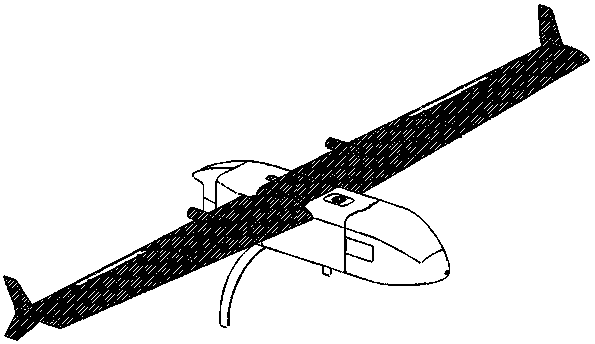
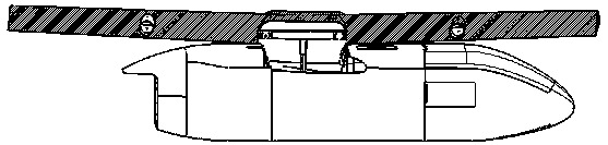
Rotatable and telescopic plane wing connection structure
A technology for connecting structures and wings, applied in the direction of wing adjustment, etc., can solve the problems of many operators and maintenance personnel, inaccurate positioning, and long time-consuming, and achieve the effects of saving installation and debugging time, fast positioning, and convenient operation
- Summary
- Abstract
- Description
- Claims
- Application Information
AI Technical Summary
Problems solved by technology
Method used
Image

Examples
Embodiment 1
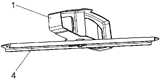
[0025] The present application is a rotatable and telescopic wing connection structure, which includes an outer cylinder 1, an inner cylinder 2, a central axis 3 and a fuselage fixed support 4. A limiting groove 8 is arranged in the outer cylinder through hole 7 of the outer cylinder 1, and the bottom The outer cylinder limit boss 9 is provided; the inner cylinder through hole 11 of the inner cylinder 2 is a square hole, the lower end of the inner cylinder through hole 11 is provided with the lower limit boss 10 of the inner cylinder, and the outer wall of the inner cylinder 2 is provided with a rotation limit boss. Platform 12, the upper end of the inner cylinder 2 is provided with an inner cylinder upper limit platform 13; the central axis is a square shaft, and the upper end of the central axis is provided with a central axis upper limit boss 15; Can slide along the inner cylinder, the upper limit boss 15 of the central axis is limited to the lower limit boss 10 of the inner...
Embodiment 2
[0027] The present application is a rotatable and telescopic wing connection structure, which includes an outer cylinder 1, an inner cylinder 2, a central axis 3 and a fuselage fixed support 4. A limiting groove 8 is arranged in the outer cylinder through hole 7 of the outer cylinder 1, and the bottom The outer cylinder limit boss 9 is provided; the inner cylinder through hole 11 of the inner cylinder 2 is a square hole, the lower end of the inner cylinder through hole 11 is provided with the lower limit boss 10 of the inner cylinder, and the outer wall of the inner cylinder 2 is provided with a rotation limit boss. Platform 12, the upper end of the inner cylinder 2 is provided with an inner cylinder upper limit platform 13; the central axis is a square shaft, and the upper end of the central axis is provided with a central axis upper limit boss 15; Can slide along the inner cylinder, the upper limit boss 15 of the central axis is limited to the lower limit boss 10 of the inner...
Embodiment 3
[0029] The following are the installation and implementation steps of the rotatable telescopic structure that does not disengage the connection of the wing and the fuselage:
[0030] The outer cylinder and the rib of the wing are integrated to connect the outer cylinder 1 with the wing. The outer cylinder 1 is provided with an outer cylinder through hole 7, a limiting groove 8, and an outer cylinder limiting boss 9;
[0031] Put the inner cylinder 2 into the through hole 7 of the outer cylinder, and then put the central axis 3 into the through hole 11 of the inner cylinder, and insert the anti-ejection bushing 5 at the upper end of the through hole 7 of the outer cylinder to limit the ejection of the inner cylinder 2. cylinder and protect the inner parts of the outer cylinder;
[0032] The wing is connected with the fuselage, and the lower end of the central axis 7 is installed into the fixed support 4 of the fuselage, and the quick release pin 6 is inserted into the pin hole ...
PUM
 Abstract
Description
Claims
Application Information
 - R&D
- Intellectual Property
- Life Sciences
- Materials
- Tech Scout
- Unparalleled Data Quality
- Higher Quality Content
- 60% Fewer Hallucinations
Browse by: Latest US Patents, China's latest patents, Technical Efficacy Thesaurus, Application Domain, Technology Topic, Popular Technical Reports.
© 2025 PatSnap. All rights reserved.Legal|Privacy policy|Modern Slavery Act Transparency Statement|Sitemap|About US| Contact US: help@patsnap.com