Leakage plugging pipe clip device and locking device for leak plugging pipe clip

A technology of locking device and leaking pipe clamp, applied in the direction of pipe/pipe joint/pipe fitting, pipe element, mechanical equipment, etc., can solve the problems of difficult operation, unsatisfactory locking requirements, high cost, high automation The effect of high probability of success and high installation efficiency

Active Publication Date: 2021-03-30
SHENZHEN OFFSHORE OIL ENG UNDERWATER TECH CO LTD
View PDF6 Cites 0 Cited by
  • Summary
  • Abstract
  • Description
  • Claims
  • Application Information

AI Technical Summary

Problems solved by technology

However, since the maintenance of deep water pipelines is difficult and the cost is several times higher than that of shallow water pipelines, research on corresponding emergency maintenance plans and development of supporting maintenance tools for the leakage of deep water pipelines are of great importance to ensure the safe production of oil and gas fields. important meaning
[0003] At present, the plugging pipe clips for sea pipes operated by divers within 300 meters and the plugging pipe clips for deep-water sea pipes operated by ROVs above 300 meters in China are all fixed by bolt locking. When installing by ROV in waters above 300 meters, due to the large number of them, ROV operation torque wrenches are required to install one by one. The underwater operation is very difficult and the efficiency is extremely low. Card test failure and other risks, the effect is very poor

Method used


Image

  • Leakage plugging pipe clip device and locking device for leak plugging pipe clip
  • Leakage plugging pipe clip device and locking device for leak plugging pipe clip
  • Leakage plugging pipe clip device and locking device for leak plugging pipe clip

Examples


Embodiment Construction

[0037] In order to have a clearer understanding of the technical features, purposes and effects of the present invention, the specific implementation manners of the present invention will now be described in detail with reference to the accompanying drawings.

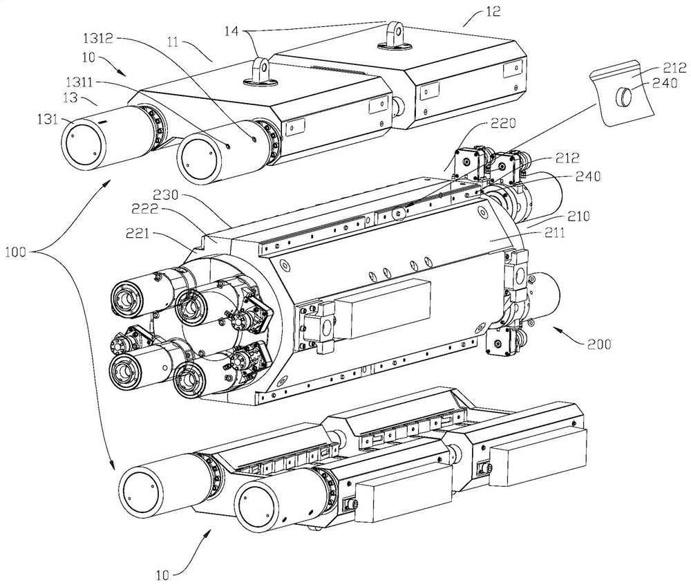
[0038] figure 1 Some preferred embodiments of the leakage plugging pipe clamping device of the present invention are shown. The plugging device can be used for plugging and maintenance of sea pipes in shallow waters within 300 meters, and can also be used for plugging and maintenance of deep-water sea pipes with a water depth of more than 300 meters. This invention gets rid of the traditional bolt locking method only The restriction that divers can enter the water for maintenance has created a new locking method, which is controlled by the ROV operation and control system to achieve unmanned underwater operation and maintenance to achieve locking, which can greatly improve the efficiency and efficiency of ROV underwater...


PUM


Abstract

The invention relates to a leaking stoppage pipe clamp device and a locking device for a leaking stoppage pipe clamp. The locking device comprises at least one locking unit. The locking units are arranged on an opening in one side or openings in two opposite sides of the leaking stoppage pipe clamp. Each locking unit comprises a first locking module and a second locking module which are arranged in a spaced manner and can move in the opposite direction. Each first locking module comprises a first clamping groove. Each second locking module comprises a second clamping groove. Each second clamping groove and the corresponding first clamping groove cooperate mutually to be arranged on the leaking stoppage pipe clamp in a clamped manner. A first locking and connecting part arranged in a wedgeshape is arranged on at least one side wall, arranged in the moving direction, of each first clamping groove. A second locking and connecting part arranged in a wedge shape and arranged in the direction opposite to the corresponding first locking and connecting part is arranged on at least one side wall, arranged in the moving direction, of each second clamping groove. The first locking and connecting parts and the second locking and connecting parts cooperate with the leaking stoppage pipe clamp for locking. The locking device has the advantages of being high in automation degree, simple in structure, easy to operate, high in installing efficiency and high in success possibility.

Description

technical field [0001] The invention relates to the maintenance technology of sea pipes, more specifically, to a leak-stopping pipe clamping device and a locking device for leak-stopping pipe clamping. Background technique [0002] In recent years, the number of deep-water marine pipelines has been increasing. Due to the long-term design and construction of marine pipelines, marine environment, pipeline corrosion, and changeable media, accidents of deep-water marine pipeline leakage have become more and more frequent. This sudden leakage of deep-water sea pipelines poses a huge threat to oil and gas field production and the marine environment. Once the sea pipeline is damaged, it will cause great losses to the operation of deepwater oil and gas fields. In order to reduce huge economic losses such as marine environmental pollution and crude oil production shutdown, it is particularly important to repair damaged pipelines safely, quickly and reliably. However, since the main...

Claims


Application Information

Patent Timeline
Patent Type & Authority Patents(China)
IPC IPC(8): F16L55/16
CPCF16L55/16
Inventor 齐兵兵曲有杰林守强柳宇张忠扬赵拥军段亚辉朱国侨
Owner SHENZHEN OFFSHORE OIL ENG UNDERWATER TECH CO LTD
Why Eureka
Try Eureka