
Device for positioning placement position of ADAS calibration target plate and positioning method

A technology for calibrating device and target board, applied in the direction of using optical devices, measuring devices, instruments, etc., can solve the problems of increasing data transmission and processing burden, cumbersome steps, complex calibration, etc.

Pending Publication Date: 2019-12-06
YANTAI UNIV
View PDF1 Cites 13 Cited by
  • Summary
  • Abstract
  • Description
  • Claims
  • Application Information

AI Technical Summary

Problems solved by technology

Although this method can eliminate some human errors to a certain extent, it has the following disadvantages: First, the operation is cumbersome. After the wheel alignment is completed, the target plate of the wheel alignment instrument must be disassembled, and then a new clamp and a new fixture should be installed on the wheel. The second is that the deformation of the rim or the installation error of the fixture may cause measurement errors. Although the installation of the fixture of the wheel aligner cannot eliminate the error, the measurement process has been dynamically compensated, so these factors can be corrected without affect the measurement
However, due to the high cost of the camera, and the simultaneous acquisition of images by multiple cameras increases the burden of data transmission and processing, generally only one additional camera is used, which is inserted in turn at both ends of the beam of the ADAS calibration board for adjustment, and the adjustment efficiency is not high enough. Another On the one hand, due to the complicated calibration of the relative position between the camera and the beam of the ADAS calibration board, the steps are cumbersome and inconvenient to use

Method used


Image

  • Device for positioning placement position of ADAS calibration target plate and positioning method
  • Device for positioning placement position of ADAS calibration target plate and positioning method
  • Device for positioning placement position of ADAS calibration target plate and positioning method

Examples


Embodiment 1

[0076] Embodiment 1. An auxiliary ADAS calibration device

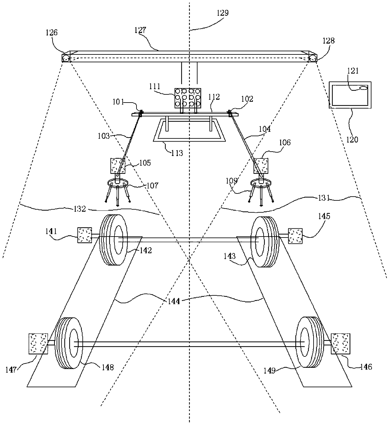
[0077] like figure 1 As shown, an auxiliary ADAS calibration device includes fixed terminals 101, 102, connecting rods 103, 104, positioning target boards 105, 106, positioning target board support frames 107, 109, ADAS calibration board 111, support frame beams 112, wheels Cameras 126, 128 of the locator, target boards 141, 145, 146, 147 of the wheel locator, and a working host 120;

[0078] The ADAS calibration board 111 is placed in front of the vehicle,

[0079] The ADAS calibration plate 111 is fixed at the middle position of the support frame beam 112, and the support frame beam 112 is placed on the support base 113 to realize convenient adjustment of the placement position of the ADAS calibration plate 111,

[0080] One end of the connecting rods 103, 104 is fixedly connected to the positioning target boards 105, 106 respectively, and the other end is movably connected to the support frame beam 112 through th...

Embodiment 2

[0098] Embodiment 2, Auxiliary ADAS calibration device with a single set of connecting rod, fixed terminal, positioning target board and positioning target board support frame

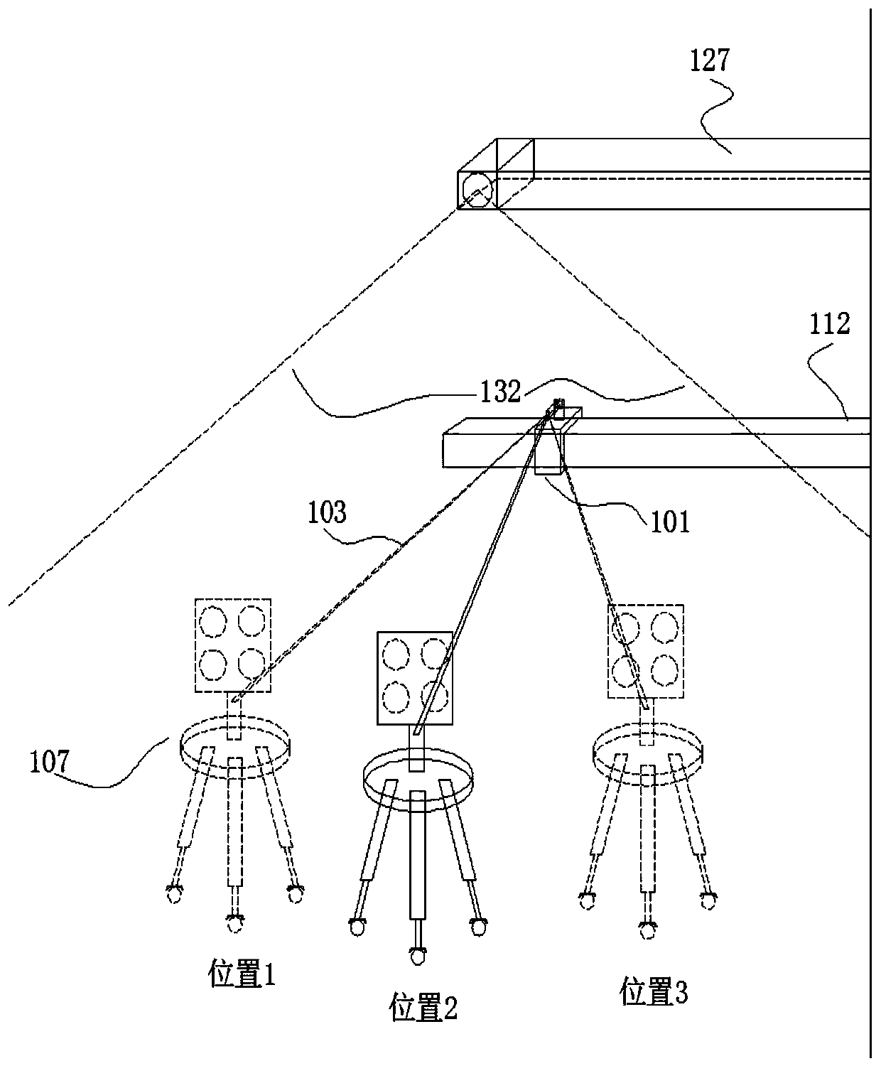
[0099] In embodiment 1, the number of connecting rods, fixed terminals, positioning target boards and positioning target board support frames in the auxiliary ADAS calibration device is two, and each different part is connected to each other to form a group, so that the auxiliary ADAS calibration device includes two A group of functional parts, each group is connected to the two ends of the crossbeam of the ADAS calibration equipment, and when the auxiliary ADAS calibration device is connected to the ADAS calibration equipment, the two sets of functional parts need to be connected to the two ends of the ADAS calibration equipment through fixed terminals.

[0100] However, as other possible options for this example, this example can also be set as follows:

[0101] In order to save costs, the two sets o...

Embodiment 3

[0102] Embodiment 3, using the auxiliary ADAS calibration device of embodiment 1 or 2 to locate the positioning method of the ADAS target board

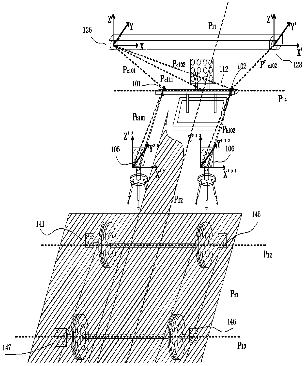
[0103]The auxiliary ADAS calibration device is placed directly in front of the vehicle to be calibrated, between the wheel aligner and the vehicle to be calibrated, and then the wheel aligner is used to place the ADAS calibration equipment so that the target identification (positioning target boards 105, 106 and the target boards 141, 145, 146, 147 of the wheel aligner fixed on the wheel rims 142, 143, 148, 149 are simultaneously in the field of view 132 and 131 of the cameras 126, 128 of the wheel aligner, so that the wheel aligner can be utilized The instrument simultaneously measures the spatial position of the centerline 129 of the vehicle to be calibrated and the spatial position of the ADAS calibration board 111, so as to accurately place the horizontal center of the ADAS calibration board 111 in front of the vehicle at a suitab...


PUM


Abstract

The invention discloses a device for positioning the placement position of an ADAS calibration target plate and a positioning method. The device is specifically a device for assisting calibration by utilizing a wheel aligner for assistance, functions of the wheel aligner are expanded, the wheel aligner is utilized to obtain the vehicle space position information, and an ADAS calibration plate is placed at an accurate position relative to a vehicle according to specification standards. The method comprises steps of acquiring a spatial position Pl1 of a to-be-calibrated vehicle center line, a spatial position Pf2 of a to-be-calibrated vehicle center line plane, a spatial position Pc111 of the ADAS calibration plate and a spatial position Pl4 of an ADAS calibration equipment support frame cross beam relative to a camera by using the device, namely, determining the accurate position of the ADAS calibration plate 111 relative to the to-be-calibrated vehicle. The method is advantaged in thatthe method is simple to operate, convenient to calibrate and high in accuracy, and working efficiency is improved quickly and conveniently.

Description

technical field [0001] The invention relates to a device and method for placing an ADAS calibration target board at an accurate position relative to a vehicle, in particular to a device for placing the calibration target board used for calibrating ADAS at a suitable position relative to the vehicle through real-time measurement by a wheel aligner and methods. Background technique [0002] The current ADAS (Advanced Driver Assistant Systems, Advanced Driver Assistance System) mainly uses sensors such as cameras and radars to obtain road condition information. Therefore, it is very necessary to calibrate ADAS during installation and use of ADAS. This is related to whether ADAS can provide correct assistance to drivers. ADAS calibration mainly uses the ADAS calibration board to calibrate sensors such as cameras and radars. During the calibration process, the position of the ADAS calibration board relative to the vehicle is required. Only by performing ADAS calibration under...

Claims


Application Information

Patent Timeline
Patent Type & Authority Applications(China)
IPC IPC(8): G01B11/00
CPCG01B11/00
Inventor 毕远伟孙海卫马文明胡潇琨阎维青李瑞旭潘庆先
Owner YANTAI UNIV
Learn More