

Low-energy electron diffractometer
A low-energy electron diffraction and electron technology, used in instruments, material analysis using wave/particle radiation, scientific instruments, etc., can solve the problems of high price, disadvantageous high-quality pulsed electrons, and low emission current of field emission electron guns, and achieve debugging. Simple, avoid geometric configuration difficulties, simple structure effect
Active Publication Date: 2019-12-06
SHANGHAI INST OF MICROSYSTEM & INFORMATION TECH CHINESE ACAD OF SCI
View PDF7 Cites 0 Cited by
- Summary
- Abstract
- Description
- Claims
- Application Information
AI Technical Summary
Problems solved by technology
However, the electron gun and detector of the current low-energy electron diffractometer are located on the front of the sample, and the laser beam can only be incident from the side of the needle tip, which is not conducive to the generation of high-quality pulsed electrons; at the same time, although the field emission electron gun has a simple structure, good monochromaticity and The advantages of easy generation of electron pulses, due to the high price of large-scale high-sensitivity two-dimensional detectors (such as multi-channel plates) and the small emission current of field emission electron guns, it is not easy to be applied in conventional low-energy electron diffractometers
Method used
View moreImage
Smart ImageViewing Examples

Examples
Embodiment approach
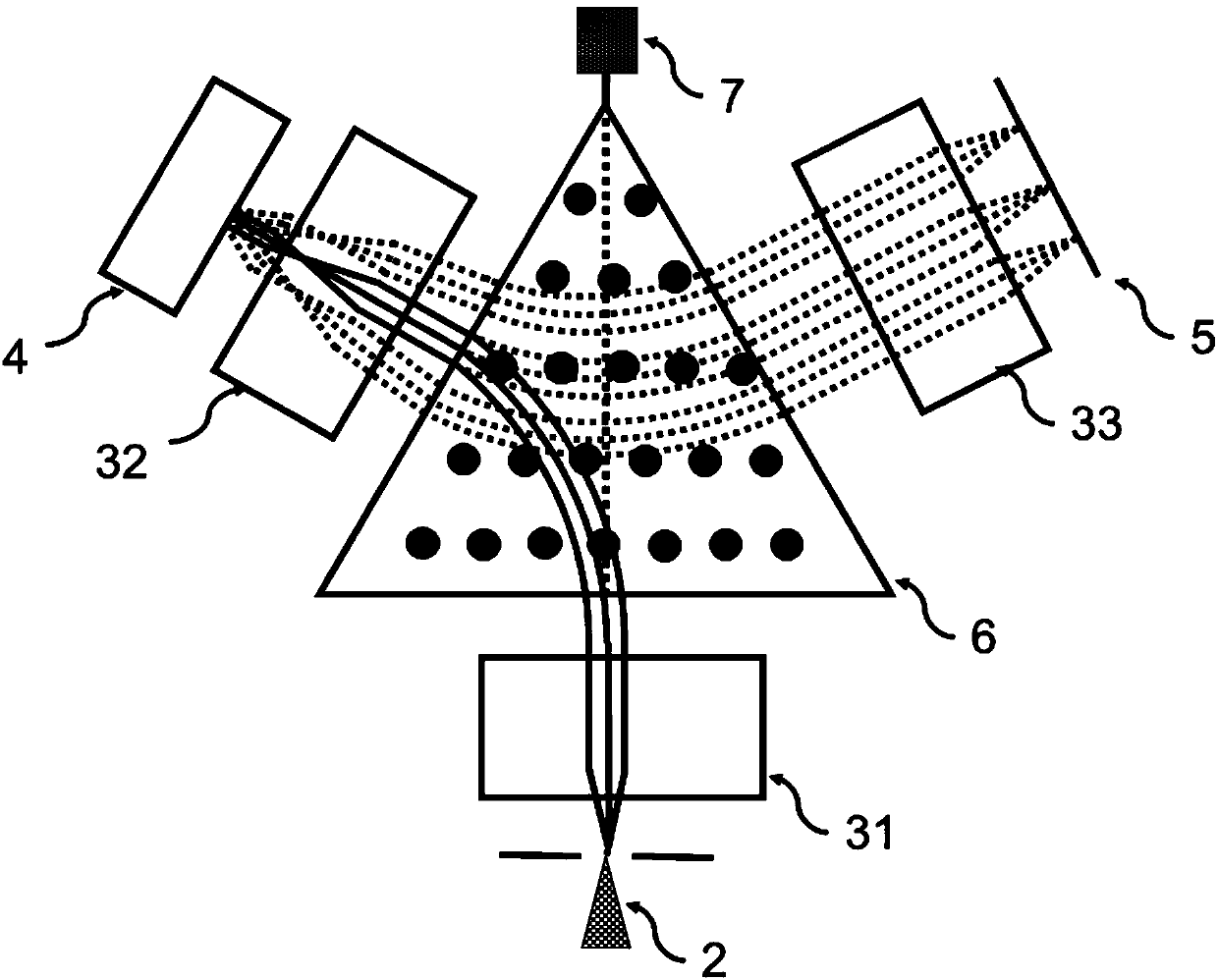
[0040] Specifically, the two-dimensional image-type electron detector 5 may be any device capable of recording electron intensity distribution. As an embodiment of the present invention, the two-dimensional image electron detector 5 is composed of a micro-channel plate (Micro-channel Plate, MCP), a fluorescent plate and a high-sensitivity camera. As another embodiment of the present invention, the two-dimensional image electron detector 5 is composed of a microchannel plate and a delay line detector (Delay Line Detector, DLD).
Login to View More PUM
 Abstract
The invention provides a low-energy electron diffractometer. The diffractometer comprises an electron generation device, a charged particle optical system, a sample and a two-dimensional image type electron detector, wherein the electron generation device is used for generating electrons, the charged particle optical system comprises a magnetic field and a non-axisymmetric electric lens group, themagnetic field is used for separating motion tracks of incident and emergent charged particles and realizing deflection of motion directions of the charged particles, and the non-axisymmetric electric lens group is used for compensating asymmetry of magnetic field optical characteristics in vertical and parallel magnetic field directions, reducing aberration and enabling a charged particle beam to be imaged on an image plane in two directions of the vertical magnetic field direction and the parallel magnetic field direction at the same time. The low-energy electron diffractometer is advantaged in that incident and emergent charged particle orbits can be separated, so geometric configuration difficulty of all parts is avoided, low-energy electron diffraction measurement without electron gun shadows is realized, and time-resolved low-energy electron diffraction measurement is more convenient.
Description
technical field [0001] The invention relates to the fields of charged particle optics and low-energy electron diffraction, in particular to a low-energy electron diffractometer. Background technique [0002] Electron lens systems have been used in a wide range of applications, ranging from picture tubes in the first generation of televisions to scientific instruments such as electron energy analyzers. Magnetic fields and magnetic lens systems play an important role in the imaging of high-energy electron and ion beams. The time-reversal antisymmetry of magnetic fields to moving charged particles has been applied to separate the orbits of incoming and outgoing particles. Magnetic fields have different optical properties for charged particles in directions perpendicular to and parallel to the magnetic field. In the direction of the vertical magnetic field, due to the effect of the Loren magnetic force, the charged particles emitted from the same point will converge again afte...
Claims
Login to View More Application Information
Patent Timeline
 Patent Type & AuthorityApplications(China)
IPC IPC(8): G01N23/20058
CPCG01N23/20058G01N2223/0565
Inventor乔山
OwnerSHANGHAI INST OF MICROSYSTEM & INFORMATION TECH CHINESE ACAD OF SCI