Current sharing control method and device, equipment and computer readable storage medium

A technology of flow control and current sharing bus, which is applied in the field of communication, and can solve problems such as deviation of current sharing control, influence on system current sharing effect, system reliability, etc.

Active Publication Date: 2019-12-06
ZTE CORP
View PDF9 Cites 2 Cited by
  • Summary
  • Abstract
  • Description
  • Claims
  • Application Information

AI Technical Summary

Problems solved by technology

The voltage information obtained by sampling is directly used for current sharing control, and the difference in sampling voltage information will lead

Method used


Image

  • Current sharing control method and device, equipment and computer readable storage medium
  • Current sharing control method and device, equipment and computer readable storage medium
  • Current sharing control method and device, equipment and computer readable storage medium

Examples


Embodiment 1

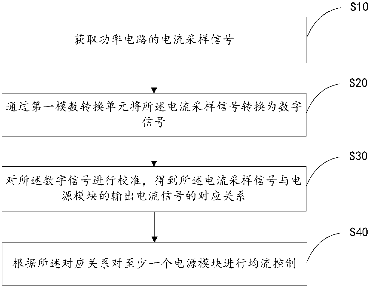
[0056] Such as figure 1 As shown, in this embodiment, a current sharing control method includes:

[0057] S10. Obtain a current sampling signal of the power circuit;

[0058] S20. Convert the current sampling signal into a digital signal by using a first analog-to-digital conversion unit;

[0059] S30. Calibrate the digital signal to obtain a corresponding relationship between the current sampling signal and the output current signal of the power module;

[0060] S40. Perform current sharing control on at least one power module according to the correspondence relationship.

[0061] In this embodiment, by converting and calibrating the sampling signal, the corresponding relationship between the sampling signal and the output current is obtained, which eliminates the deviation caused by the difference of the sampling circuit to the current sharing control of the parallel power supply module, and improves the current sharing effect of the power supply module , improving the reli...

Embodiment 2

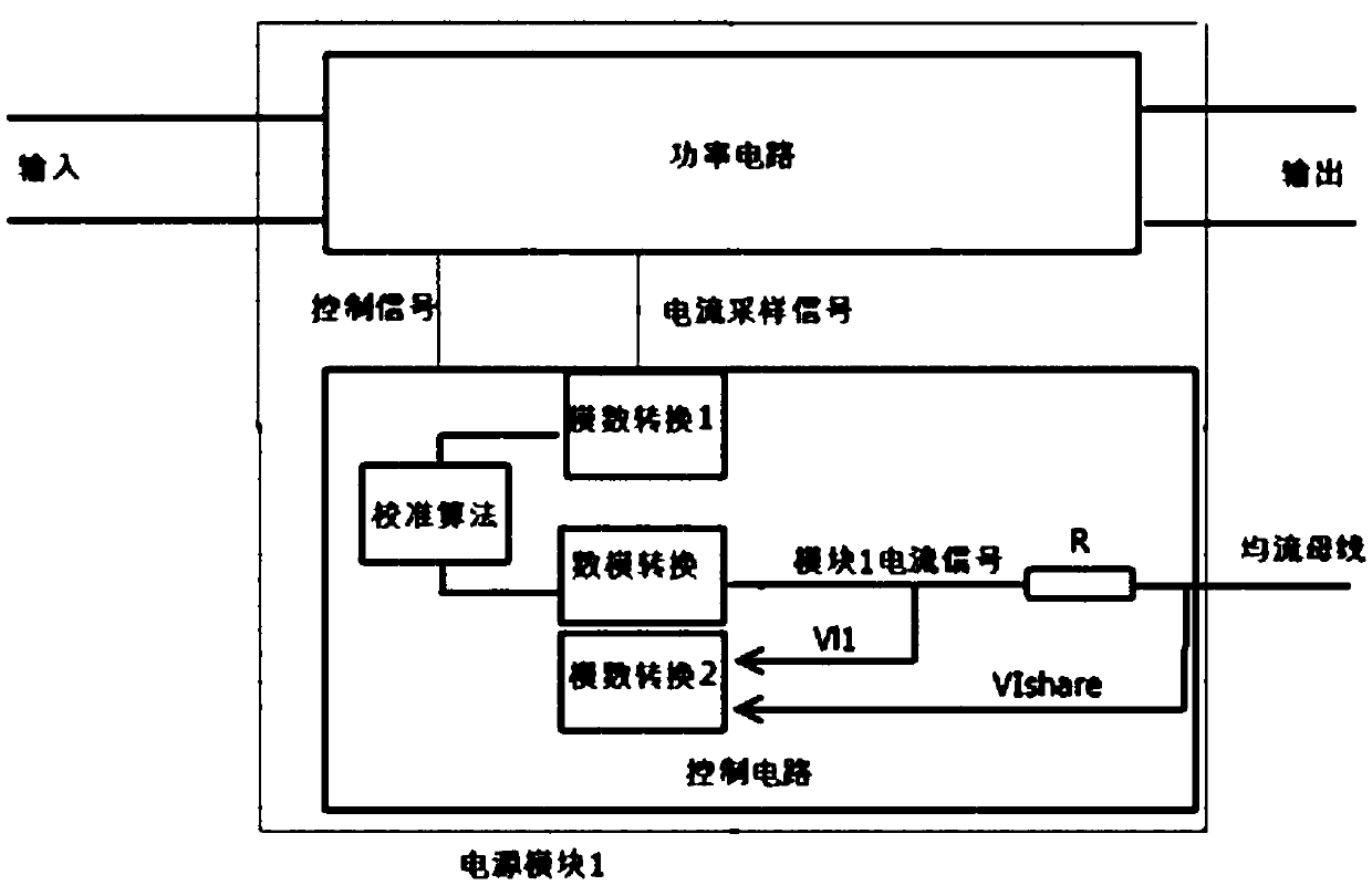
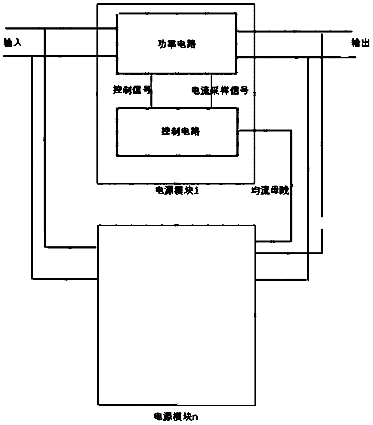
[0080] Such as Figure 6 As shown, the current sharing bus resistance R is set inside the power module, but connected to the control circuit externally. At this time, there is a functional relationship between the current sampling signal and the output current signal of the power module, and the quadratic curve fitting method can be used to The digital signal is calibrated to obtain the functional relationship between the current sampling signal and the output current signal of the power module; for example, V=A*I 2 +B*I+C, in some occasions, the output voltage and current are not necessarily linear, and may even be a function of 3 or more times. The current sharing method of the current sharing bus can be average current sharing, maximum current sharing or other current sharing methods.

[0081] As another example, Figure 6 The current sampling signal and the output current signal of the power module can also be represented by a piecewise linear relationship, and the digit...

Embodiment 3

[0085] Such as Figure 7 As shown, the current-sharing bus resistor R is set outside the power module, and the module itself has calculated the current value before, so no digital-to-analog conversion is performed on the output current. The calibration algorithm can be linear calibration, high-order function calibration or other custom calibration algorithms. The current sharing control method can be the average current sharing similar to the figure below, or the maximum current sharing or other current sharing algorithms.


PUM


Abstract

The invention discloses a current sharing control method and device, equipment and a computer readable storage medium and belongs to the technical field of communication. The method comprises steps ofacquiring a current sampling signal of a power circuit; converting the current sampling signal into a digital signal through a first analog-to-digital conversion unit; calibrating the digital signalto obtain the corresponding relationship between the current sampling signal and an output current signal of a power supply module; and performing current sharing control of at least one power supplymodule according to the corresponding relationship. The method is advantaged in that deviation caused by difference of sampling circuits to current sharing control of the parallel power supply modulesis eliminated, the current sharing effect of the power supply modules is improved, and system reliability is improved.

Description

technical field [0001] This article relates to the technical field of communications, and in particular to a current sharing control method, device, equipment, and computer-readable storage medium. Background technique [0002] In the field of communication power supply, in order to meet the requirements of load power and power supply reliability, it is very important to use multiple power supplies in parallel to achieve high power output. The parallel use of power modules has the advantages of easy expansion, good compatibility, redundant backup, etc. These advantages promote the research and development of parallel current sharing technology in the power supply field. [0003] When multiple identical power supplies are working in parallel, due to the difference in circuit component parameters, the output current of each power supply is different, resulting in different electrical stress and thermal stress when different power supplies are working, which affects the reliabl...

Claims


Application Information

Patent Timeline
IPC IPC(8): G01R19/25G05F1/625
CPCG01R19/25G05F1/625H02M1/0009H02M1/0012H02M1/0025H02M3/1584G01R19/2513
Inventor 高云任亚奇
Owner ZTE CORP
Why Eureka
Try Eureka