Front steel plate spring suspension system

A leaf spring and suspension system technology, which is applied in the direction of elastic suspension, suspension, vehicle spring, etc., can solve the problems of poor vibration damping effect, poor ride comfort, abnormal steering of the front axle, etc., so as to avoid large rearward movement and smooth The effect of improving the performance and improving the firmness

Inactive Publication Date: 2019-12-10
DONGFENG COMML VEHICLE CO LTD
View PDF11 Cites 7 Cited by
  • Summary
  • Abstract
  • Description
  • Claims
  • Application Information

AI Technical Summary

Problems solved by technology

However, the single-leaf spring may break in the first half of the forward direction after working for a long time. After the break, the corresponding front axle will directly move backward, causing abnormal steering of the front axle, which poses a safety hazard.
[0005] see figure 2 , the front leaf spring suspension system of a commercial vehicle on the market, including a leaf spring 3, the leaf spring 3 is a two-leaf spring structure, and one end of the leaf spring 3 passes through the bushing, the front leaf spring pin and the fixed end bracket 2 Fixed on the vehicle frame 1, the other end of the leaf spring 3 is fixed on the vehicle frame 1 through the lifting lug 16, the bushing, the rear leaf spring pin and the lifting lug end bracket 17, and the middle part of the leaf spring 3 is fixed on the vehicle frame 1 through a U-shaped bolt 9 is fixed on the front axle 10, a cover plate 8 is laid between the upper surface of the leaf spring 3 and the U-shaped bolt 9, and a backing plate 11 is laid between the lower surface of the leaf spring 3 and the front axle 10, so A limit block 13 is also fixed on the vehicle frame 1, and the limit block 13 is located above the front axle 10. A shock absorber 14 is arranged between the limit block 13 and the lug end bracket 17. The shock absorber One end of the shock absorber 14 is connected to the front axle 10 through the shock absorber lower bracket 12, and the other end is fixed on the vehicle frame 1 through the shock absorber upper bracket 15. The front axle 10 is also connected with a transverse stabilizer bar 6, and the transverse stabilizer One end of the bar 6 is connected to the front axle 10 through the stabilizer bar bracket 7, and the other end is connected to the vehicle frame 1 through the boom 5 and the boom bracket 4. The leaf spring is a two-leaf leaf spring structure with heavy weight and high dynamic stiffness. Poor vibration damping effect and poor ride comfort

Method used


Image

  • Front steel plate spring suspension system
  • Front steel plate spring suspension system
  • Front steel plate spring suspension system

Examples


Embodiment 1

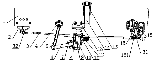
[0043] see figure 1 , a front leaf spring suspension system, comprising a vehicle frame 1 and a leaf spring 3, the front end of the leaf spring 3 in the forward direction of the vehicle is a front roll ear 32, and the front roll ear 32 passes through a bushing, a front steel plate The spring pin and the fixed end bracket 2 are fixed on the vehicle frame 1, and the rear end of the leaf spring 3 in the forward direction of the vehicle is a rear ear 31, and the rear ear 31 passes through the lifting ear 16, the bushing, and the rear steel plate. The spring pin and the lug end bracket 17 are fixed on the vehicle frame 1, and the middle part of the leaf spring 3 is fixed on the front axle 10 through the U-shaped bolt 9, and there is a pad between the upper surface of the leaf spring 3 and the U-shaped bolt 9. A cover plate 8, a backing plate 11 is placed between the lower surface of the leaf spring 3 and the front axle 10, and a limit block 13 is fixed on the vehicle frame 1, and ...

Embodiment 2

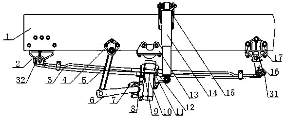
[0049] see figure 1 , a front leaf spring suspension system, comprising a vehicle frame 1 and a leaf spring 3, the front end of the leaf spring 3 in the forward direction of the vehicle is a front roll ear 32, and the front roll ear 32 is passed through a bushing, a leaf spring The pin and the fixed end bracket 2 are fixed on the vehicle frame 1, and the rear end of the leaf spring 3 in the forward direction of the vehicle is a rear ear 31, and the rear ear 31 passes through the lifting ear 16, the bushing, and the leaf spring pin. and the lug end bracket 17 are fixed on the vehicle frame 1, the middle part of the leaf spring 3 is fixed on the front axle 10 through the U-shaped bolt 9, and a cover plate is placed between the upper surface of the leaf spring 3 and the U-shaped bolt 9 8. A backing plate 11 is placed between the lower surface of the leaf spring 3 and the front axle 10, and a limit block 13 is fixed on the frame 1, and the limit block 13 is located above the fron...


PUM


Abstract

The invention discloses a front steel plate spring suspension system, and belongs to the field of heavy truck parts. The front steel plate spring suspension system comprises a frame (1) and a plate spring (3). A front spring eye (32) is arranged at the front end, in the vehicle advancing direction, of the plate spring (3) and fixed to the frame (1). A rear spring eye (31) is arranged at the rear end, in the vehicle advancing direction, of the plate spring (3) and fixed to the rear end of the frame (1). The middle of the plate spring (3) is fixed to a front axle (10) through a U-shaped bolt (9), and a shock absorber (14) is arranged between the front axle (10) and a lifting lug end support (17). The plate spring is a single leaf spring, and a protection mechanism (18) is further fixed to the frame (1). The protection mechanism (18) is located behind the lifting lug end support (17). The single leaf spring is low in weight and small in dynamic stiffness, the offset frequency is reduced,the vehicle ride comfort is improved, and the protection mechanism has the function of limiting the backward motion of a lifting lug.

Description

technical field [0001] The invention relates to the technical field of heavy-duty truck components, in particular to a front steel spring plate suspension system. Background technique [0002] The automobile suspension system refers to a connection structure system between the body, frame and wheels. When the car is driving on the road, it is subject to vibration and impact due to changes in the ground. Part of the force of these impacts will be absorbed by the tires, but most of them will be Part of it is absorbed by the suspension system between the tires and the body. [0003] At present, the development of heavy-duty trucks has been constrained by objective factors such as the implementation of national policies to control overloading and weight-based charges, rising fuel prices, and strong demands from companies and users for cost savings and operational efficiency improvements. Reducing the self-weight of heavy trucks is an important way to reduce fuel consumption. At...

Claims


Application Information

Patent Timeline
Patent Type & Authority Applications(China)
IPC IPC(8): B60G15/02B60G11/12
CPCB60G11/12B60G15/02B60G2202/11
Inventor 杜笑晨李应涛彭显威闫明星范培斌
Owner DONGFENG COMML VEHICLE CO LTD
Why Eureka
Try Eureka