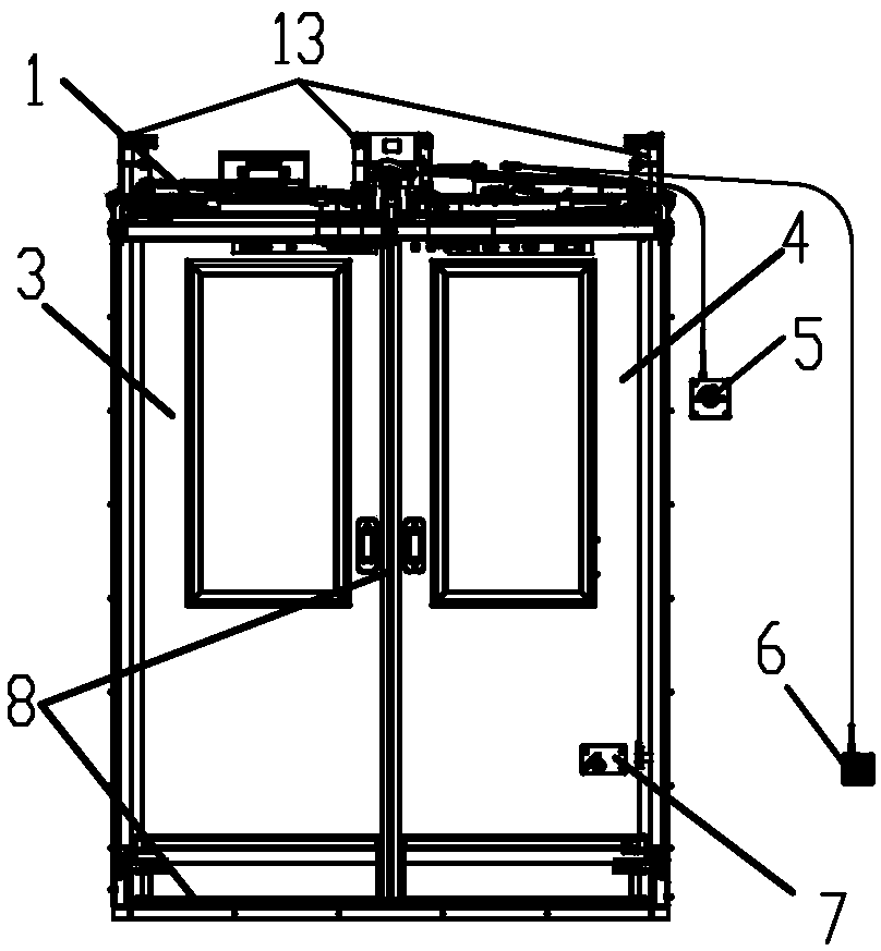
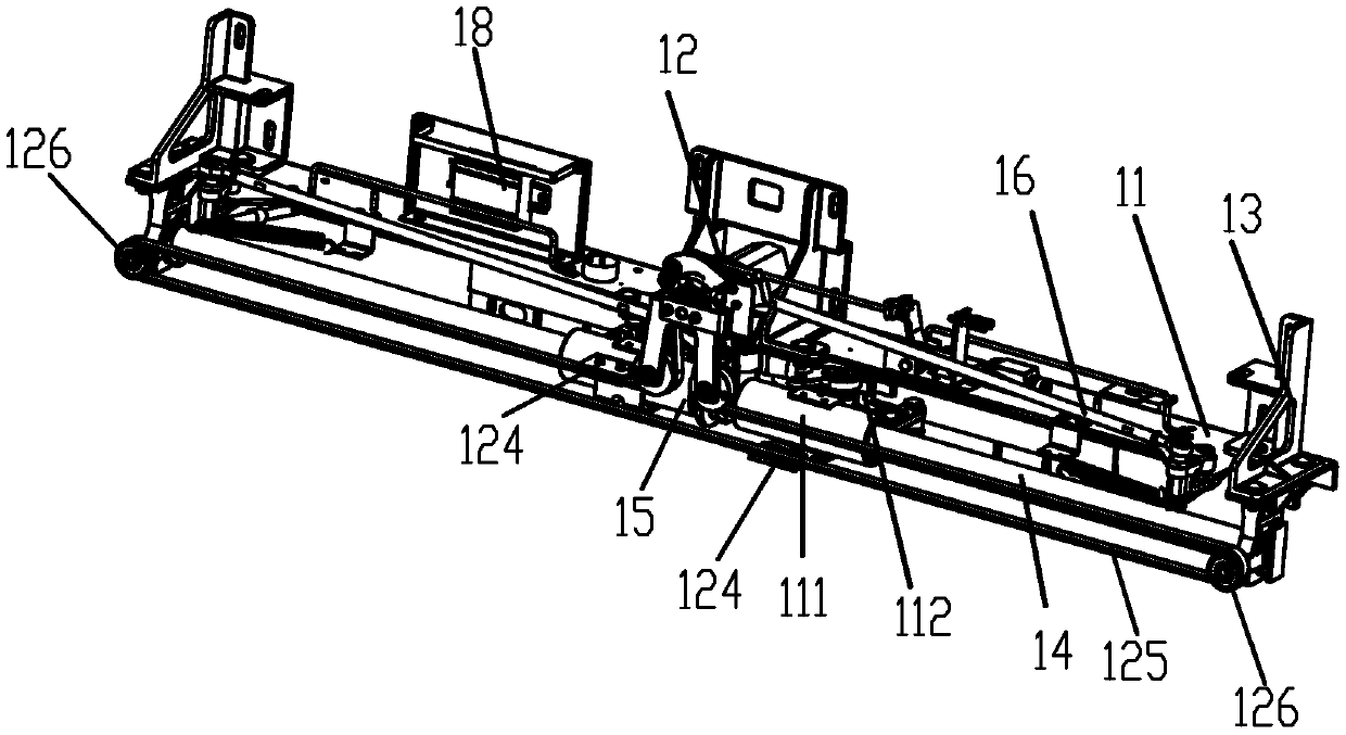
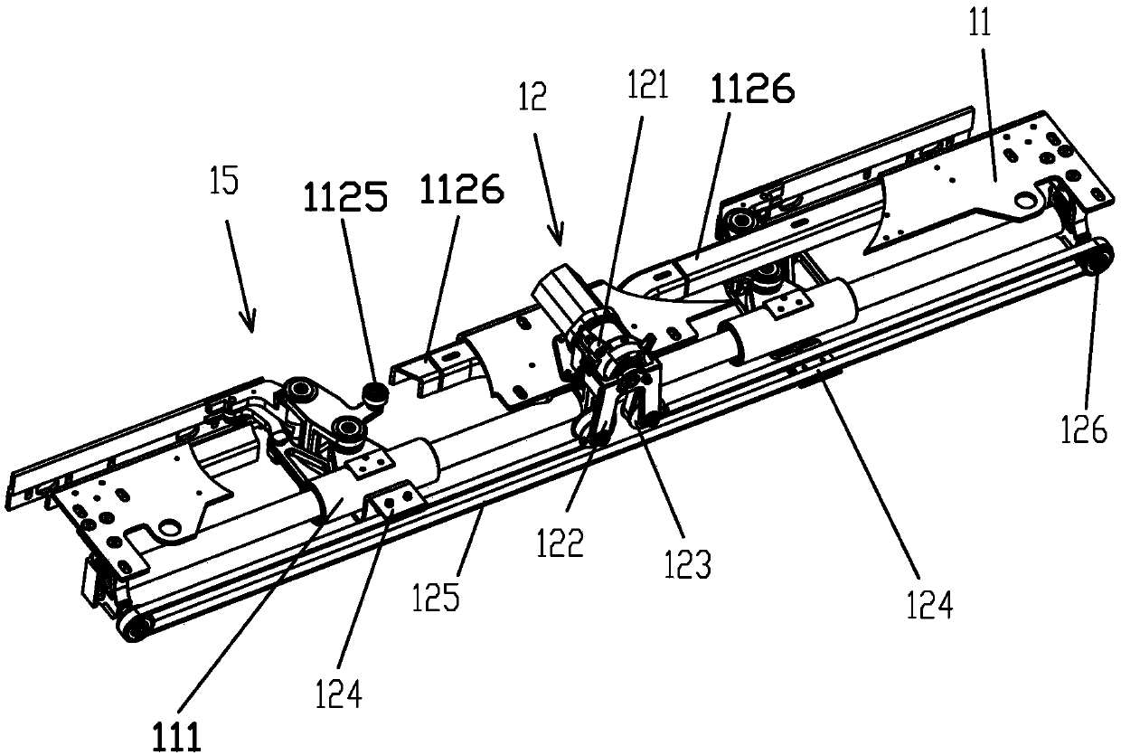
Sliding plug door driving device

A driving device and driving force technology, applied in the direction of door device, suspension device of wing leaf, door/window accessories, etc., can solve the problem that the sliding door driving device cannot realize synchronous action, etc., and achieve high safety, reliability, and door closing. Fast, simple effects

Pending Publication Date: 2019-12-10
北京天乐泰力科技发展有限公司
View PDF3 Cites 5 Cited by
  • Summary
  • Abstract
  • Description
  • Claims
  • Application Information

AI Technical Summary

Problems solved by technology

[0007] The purpose of the present invention is to solve the technical problem that the sliding door driving device in the sliding door device in the prior art cannot realize synchronous action

Method used


Image

  • Sliding plug door driving device
  • Sliding plug door driving device
  • Sliding plug door driving device

Examples


Embodiment Construction

[0042] The above and other technical features and advantages of the present invention will be described in more detail below in conjunction with the accompanying drawings.

[0043] Preferred embodiments of the present invention are described below with reference to the accompanying drawings. Those skilled in the art should understand that these embodiments are only used to explain the technical principles of the present invention, and are not intended to limit the protection scope of the present invention.

[0044] It should be noted that, in the description of the present invention, terms such as "upper", "lower", "left", "right", "inner", "outer" and other indicated directions or positional relationships are based on the terms shown in the accompanying drawings. The direction or positional relationship shown is only for convenience of description, and does not indicate or imply that the device or element must have a specific orientation, be constructed and operated in a spec...


PUM


Abstract

The invention relates to a sliding plug door driving device. The sliding plug door driving device comprises a driving mechanism and pulley link mechanisms, wherein the driving mechanism is arranged atthe middle position and can be used for providing driving force for the pulley link mechanisms which are symmetrically arranged at the left and right sides of the driving mechanism so as to implementsliding action; an action input end of each pulley link mechanism is connected with the driving mechanism; an action output end of each pulley link mechanism is connected with a left door leaf or a right door leaf; the pulley link mechanisms are correspondingly used for providing the same driving force for the left door leaf or the right door leaf which is connected with the corresponding pulleylink mechanism so that the left door leaf and the right door leaf can simultaneously move in the same direction or the opposite directions. According to the sliding plug door driving device provided by the invention, the driving mechanism is arranged at the middle position; the pulley link mechanisms are correspondingly symmetrically arranged at the two sides of the driving mechanism; moreover, the symmetrically-arranged mechanisms correspondingly act at the same time; and the sliding plug door driving device realizes precise motion in comparison with a way that one group of rod mechanisms areused for outputting power at different rod positions to implement corresponding driving.

Description

technical field [0001] The invention relates to the technical field of sliding doors, in particular to a driving device for a sliding door that can be applied to rail vehicles and public vehicles and adopts the same power output plugging action. Background technique [0002] In the prior art, along with the continuous development of my country's railway passenger transport, the airtightness, convenience and flexibility of train doors have gradually become its very important indicators. Therefore, a large number of new technologies have been adopted in the speed-up bus, and the plug door is one of them: the plug door is a product integrating gas, electricity and machinery. The so-called plug door mainly means that the door has two actions of plugging and pulling That is, when the door is closed, it is stuffed into the door of the car from the inside or outside of the car to make it closed and sealed; At present, the electric sliding doors used in some cities in the market ar...

Claims


Application Information

Patent Timeline
Patent Type & Authority Applications(China)
IPC IPC(8): E05F15/655E05F15/646E05D15/06
CPCE05D15/0608E05Y2900/506E05Y2900/51E05Y2900/531E05F15/646E05F15/655B61D19/009
Inventor 刘春梅
Owner 北京天乐泰力科技发展有限公司
Why Eureka
Try Eureka