Geological prospecting sampling device
A sampling equipment and geological exploration technology, applied in drilling equipment, undisturbed core extraction devices, wellbore/well components, etc., can solve the problems of time-consuming and laborious, tools easily stuck in the soil layer, etc., and achieve the effect of small space
- Summary
- Abstract
- Description
- Claims
- Application Information
AI Technical Summary
Problems solved by technology
Method used
Image
Examples
specific Embodiment approach 1
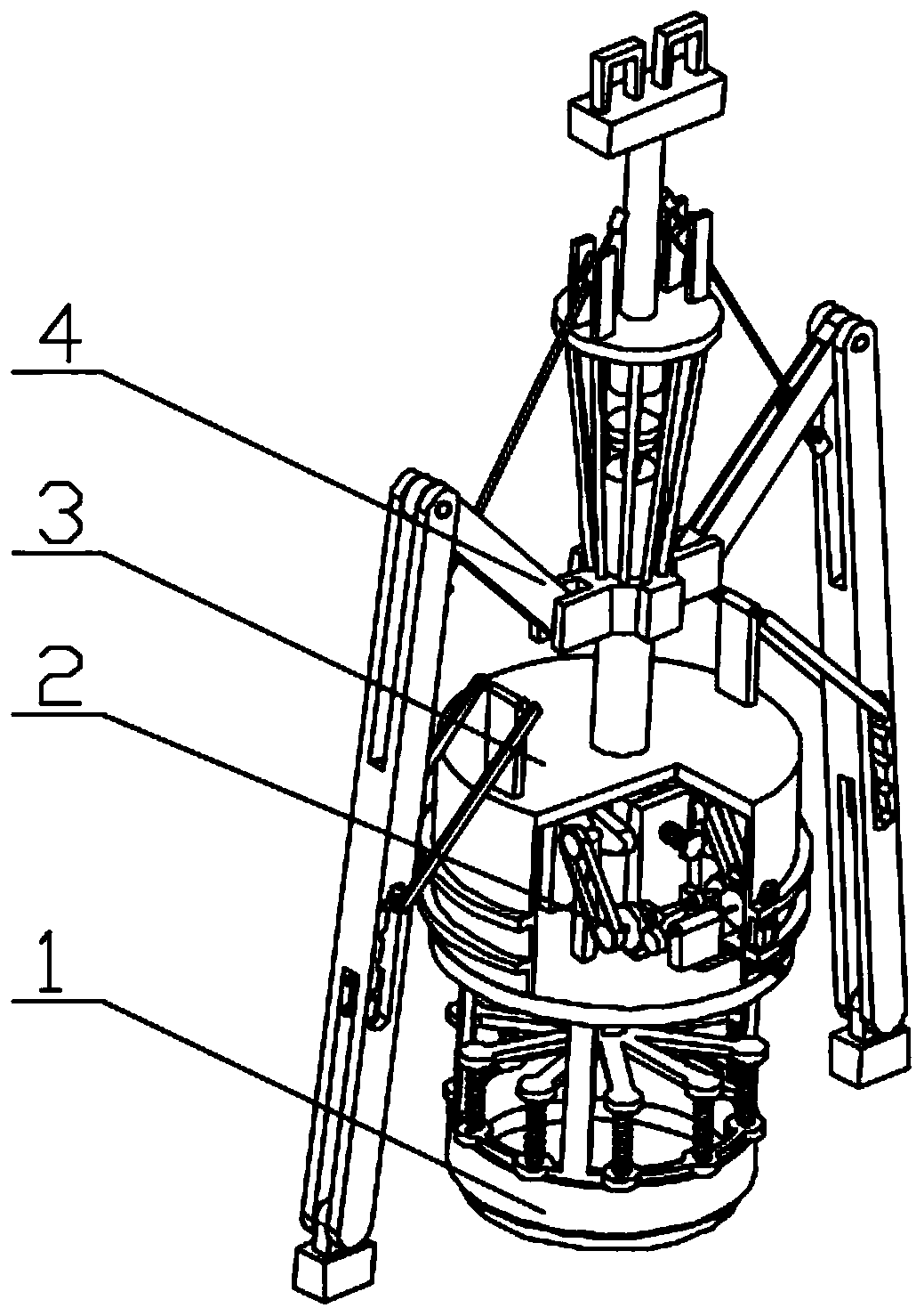
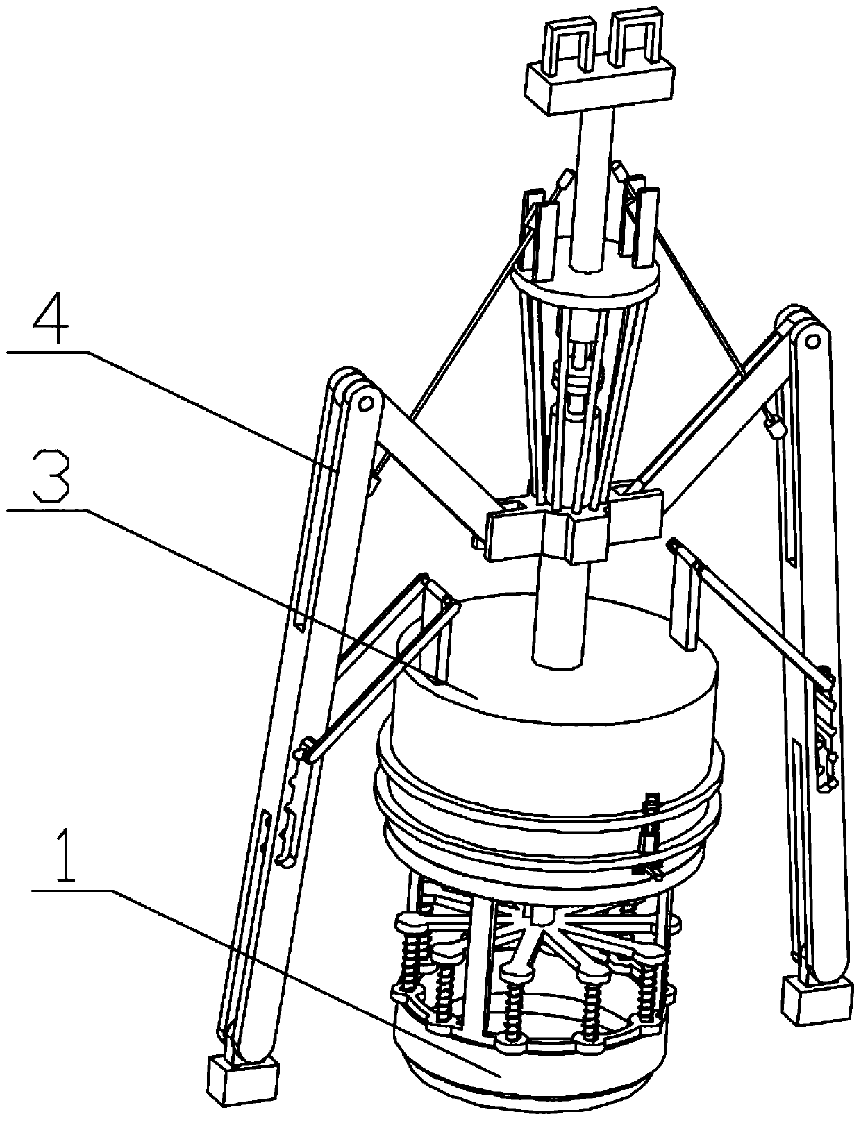
[0041] Combine below figure 1 , figure 2 , image 3 , Figure 4 , Figure 5 , Figure 6 , Figure 7 , Figure 8 , Figure 9 , Figure 10 , Figure 11 , Figure 12 , Figure 13 , Figure 14 , Figure 15 , Figure 16 , Figure 17 , Figure 18 , Figure 19 , Figure 20 , Figure 21 , Figure 22 , Figure 23 , Figure 24 , Figure 25 Describe this embodiment. The present invention relates to a sampling device, more specifically a sampling device for geological exploration, including a rotary cutter mechanism 1, a vibration drive mechanism 2, a rotating body mechanism 3, and an integral support mechanism 4. The equipment can Provide a stable support state, the equipment can cut the soil layer, the equipment can prevent the equipment from being stuck in the soil layer, the equipment can adjust the shaking speed, and the equipment can occupy a small space when it is not working.
[0042] The rotary cutter mechanism 1 is connected with the vibration driving mec...
specific Embodiment approach 2
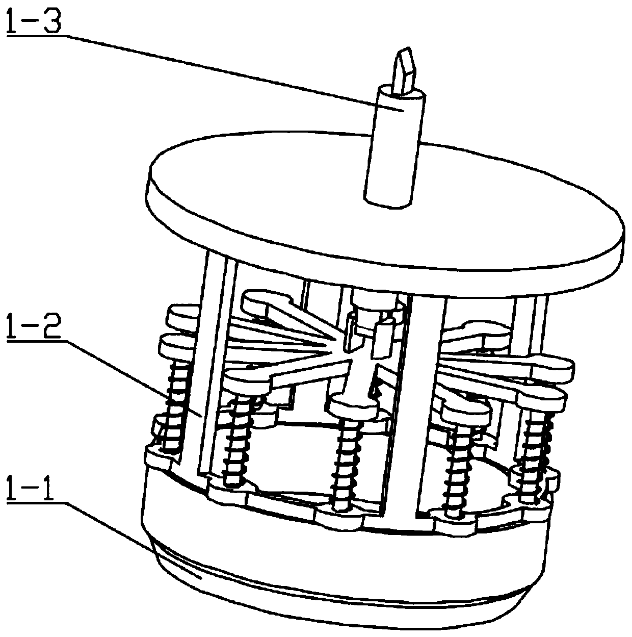
[0044] Combine below figure 1 , figure 2 , image 3 , Figure 4 , Figure 5 , Figure 6 , Figure 7 , Figure 8 , Figure 9 , Figure 10 , Figure 11 , Figure 12 , Figure 13 , Figure 14 , Figure 15 , Figure 16 , Figure 17 , Figure 18 , Figure 19 , Figure 20 , Figure 21 , Figure 22 , Figure 23 , Figure 24 , Figure 25 Describe this embodiment, this embodiment will further explain the first embodiment, the rotary tool mechanism 1 includes the executive tool mechanism 1-1, the rotating frame mechanism 1-2, the upper and lower matching rod mechanism 1-3, the executive tool mechanism 1- 1 cooperates with the rotating frame mechanism 1-2, the rotating frame mechanism 1-2 cooperates with the upper and lower matching rod mechanism 1-3, and the upper and lower matching rod mechanism 1-3 is hinged with the execution tool mechanism 1-1; the execution tool mechanism 1- 1 includes rotary knife 1-1-1, rotary knife seat 1-1-2, spring 1-1-3, spring rod 1-1...
specific Embodiment approach 3
[0046] Combine below figure 1 , figure 2 , image 3 , Figure 4 , Figure 5 , Figure 6 , Figure 7 , Figure 8 , Figure 9 , Figure 10 , Figure 11 , Figure 12 , Figure 13 , Figure 14 , Figure 15 , Figure 16 , Figure 17 , Figure 18 , Figure 19 , Figure 20 , Figure 21 , Figure 22 , Figure 23 , Figure 24 , Figure 25Describe this embodiment, this embodiment will further explain the first embodiment, the vibration drive mechanism 2 includes a reciprocating mechanism 2-1, a reciprocating support mechanism 2-2, an irregular cam mechanism 2-3, a transmission wheel mechanism 2- 4. The driving mechanism 2-5, the stepped sliding groove seat mechanism 2-6, the adjusting arm mechanism 2-7, the reciprocating mechanism 2-1 cooperates with the reciprocating support mechanism 2-2, the reciprocating mechanism 2-1 cooperates with the irregular cam The mechanism 2-3 cooperates, the connection mode of the irregular cam mechanism 2-3 and the transmission whe...
PUM
 Abstract
Description
Claims
Application Information
 - R&D
- Intellectual Property
- Life Sciences
- Materials
- Tech Scout
- Unparalleled Data Quality
- Higher Quality Content
- 60% Fewer Hallucinations
Browse by: Latest US Patents, China's latest patents, Technical Efficacy Thesaurus, Application Domain, Technology Topic, Popular Technical Reports.
© 2025 PatSnap. All rights reserved.Legal|Privacy policy|Modern Slavery Act Transparency Statement|Sitemap|About US| Contact US: help@patsnap.com


