Cross-flow air way module and air warmer

An air duct component and cross-flow technology, applied in the field of cross-flow air duct components and heaters, can solve the problems of low air volume and air speed of heaters, loss of gas speed, etc., and achieve increased air volume and air speed, short flow distance, and reduce loss. Effect

Active Publication Date: 2019-12-10
GREE ELECTRIC APPLIANCES INC
View PDF19 Cites 0 Cited by
  • Summary
  • Abstract
  • Description
  • Claims
  • Application Information

AI Technical Summary

Problems solved by technology

The air duct of the current heater is usually curved, and the gas enters from one side of the air duct and needs to be rotated by 90° or more before it can flow out from the air outlet. The he

Method used


Image

  • Cross-flow air way module and air warmer
  • Cross-flow air way module and air warmer

Examples


Embodiment Construction

[0046] In order to understand the above-mentioned purpose, features and advantages of the present invention more clearly, the present invention will be further described in detail below in conjunction with the accompanying drawings and specific embodiments. It should be noted that, in the case of no conflict, the embodiments of the present invention and the features in the embodiments can be combined with each other.

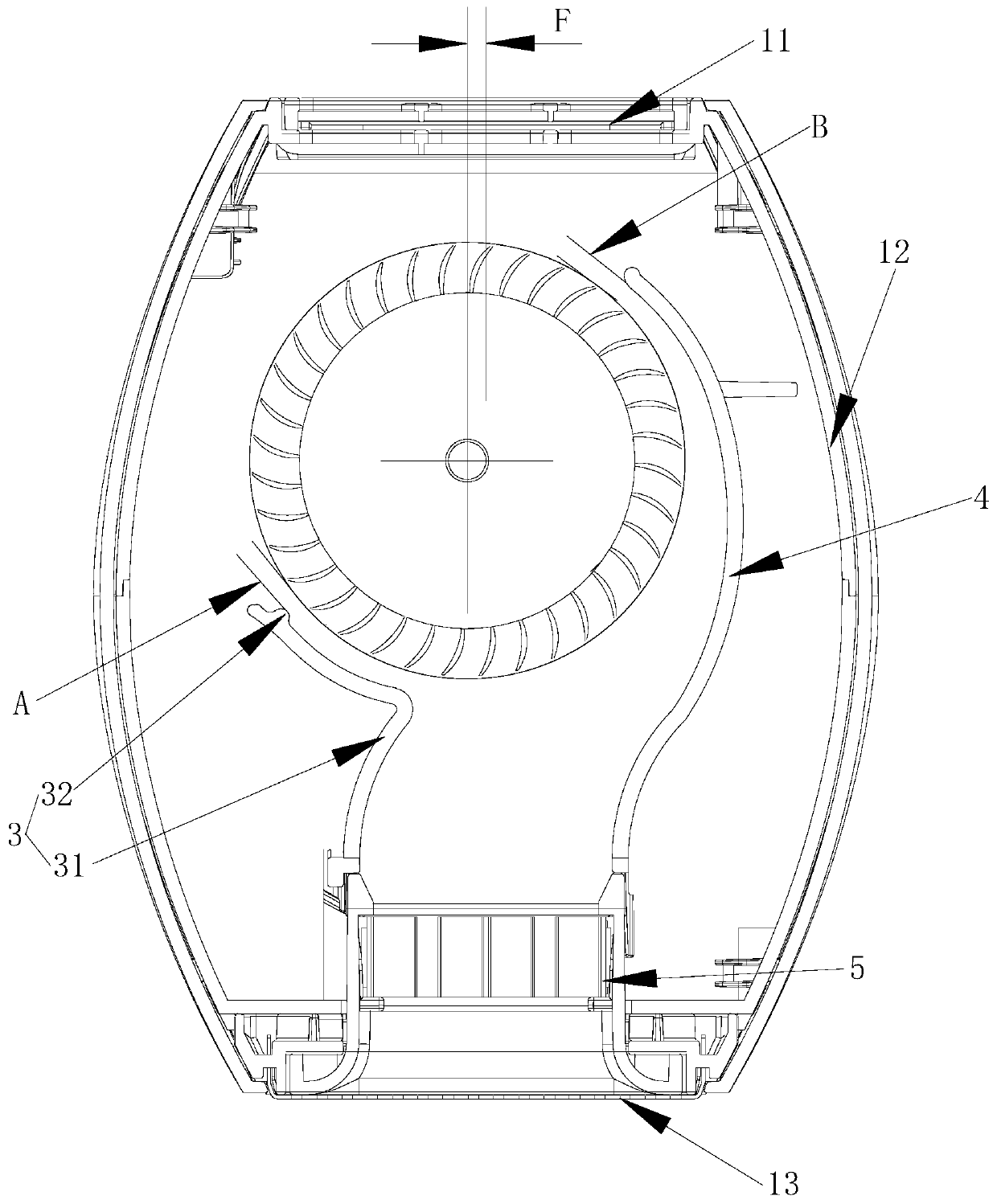
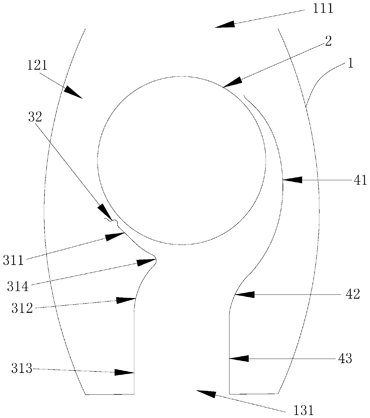
[0047] Such as figure 2 As shown, the present invention provides a cross-flow air duct assembly, which includes a housing 1, an impeller 2, a wind guiding volute 3 and a wind guiding volute 4, wherein the housing 1 has an air inlet 111, an air duct 121 and an air outlet 131, The impeller 2, the air guide volute 3 and the air guide volute 4 are all installed in the air duct 121, and the air inlet 111 and the air outlet 131 are all connected with the air duct 121, thereby forming a gas circulation channel, the air inlet 111 and the air outlet 131 They are respec...


PUM


Abstract

The invention relates to the technical field of household electrical appliances, in particular to a cross-flow air way module and an air warmer. The cross-flow air way module comprises an outer shell,an impeller, an air guide volute tongue and an air guide volute; the outer shell is provided with an air inlet, an air way and an air outlet; the air inlet and the air outlet are formed in two opposite sides of the air way, and communicate with the air way; the axis of the air inlet is parallel to the axis of the air outlet; the air guide volute and the air guide volute tongue are arranged on twoopposite sides of the air outlet; and set gaps are formed between the air guide volute tongue and the impeller and between the air guide volute and the impeller separately. The cross-flow air way module is higher in air outlet quantity and relatively higher in air speed.

Description

technical field [0001] The invention relates to the technical field of household electrical appliances, in particular to a cross-flow air duct assembly and a heater. Background technique [0002] As a household appliance with a high utilization rate, the popularity of heaters is getting higher and higher. The blades of the heater operate under the drive of the motor, and the gas enters from the air inlet, guides through the air duct, and finally blows out from the air outlet. The air duct of the current heater is usually curved, and the gas enters from one side of the air duct and needs to be rotated by 90° or more before it can flow out from the air outlet. The heater with this structure will produce a certain amount of gas. It will also lose the speed of the gas to a certain extent, resulting in relatively low air volume and wind speed of the heater. Contents of the invention [0003] (1) The technical problem to be solved by the present invention is: there are certain...

Claims


Application Information

Patent Timeline
IPC IPC(8): F24H9/00F24H3/04
CPCF24H3/0411F24H9/0063
Inventor 梁文龙柳洲梁浩王凯强王孝忱
Owner GREE ELECTRIC APPLIANCES INC
Why Eureka
Try Eureka