A kind of cooling structure of turbine blade separation, lateral rotation and re-convergence

A turbine blade and cooling structure technology, applied in the direction of blade support components, machines/engines, mechanical equipment, etc., can solve the problems of low cooling effect, short flow distance, small heat exchange area of ​​cold air and trailing edge, etc., to achieve improved Cooling effect, effect of increased heat transfer area

Active Publication Date: 2022-07-01
DALIAN UNIV OF TECH
View PDF15 Cites 0 Cited by
  • Summary
  • Abstract
  • Description
  • Claims
  • Application Information

AI Technical Summary

Problems solved by technology

This type of trailing edge split cooling structure only relies on the ribs on the trailing edge to disturb the cold air, the heat exchange area between the cold air and the trailing edge is small, the flow distance is short, and the cooling effect is low

Method used


Image

  • A kind of cooling structure of turbine blade separation, lateral rotation and re-convergence
  • A kind of cooling structure of turbine blade separation, lateral rotation and re-convergence
  • A kind of cooling structure of turbine blade separation, lateral rotation and re-convergence

Examples


Embodiment 1

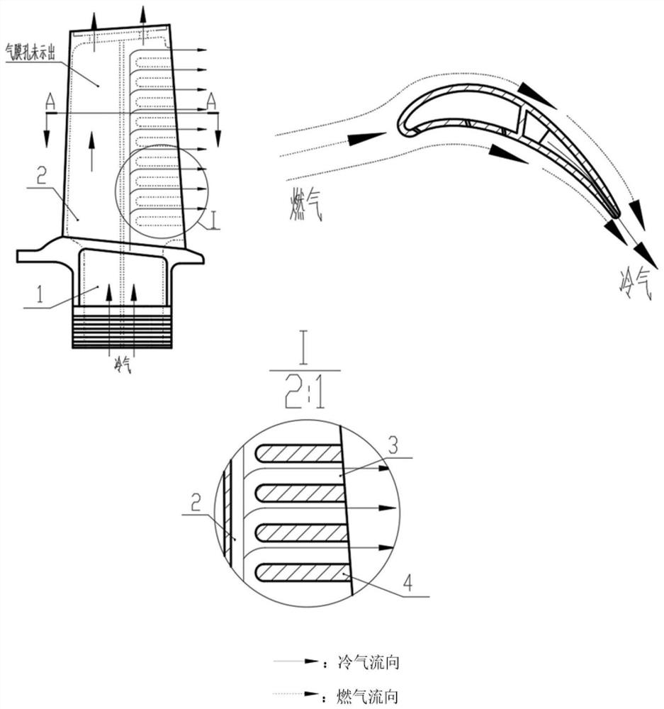
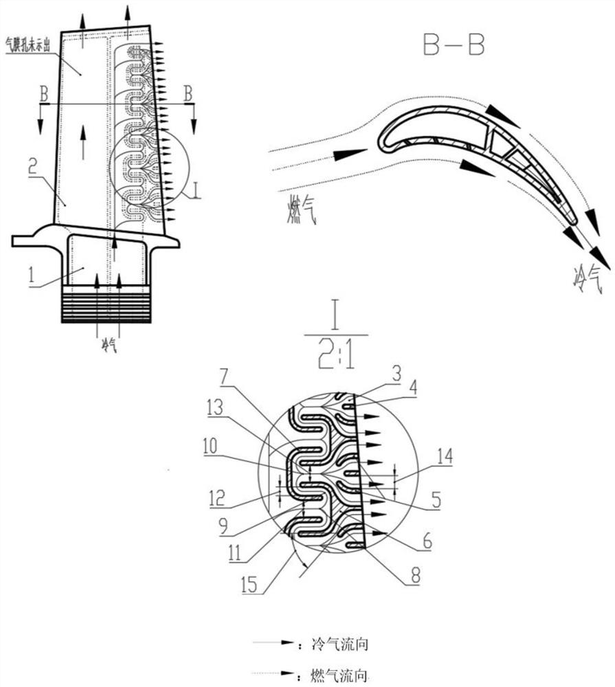
[0025] A type of cooling structure of turbine blade separation, lateral rotation and re-convergence is mainly composed of a herringbone-shaped partition rib 6, a C-shaped partition rib 7, a J-shaped partition rib 5, and a trailing edge split-slot straight rib 4. figure 2 shown.

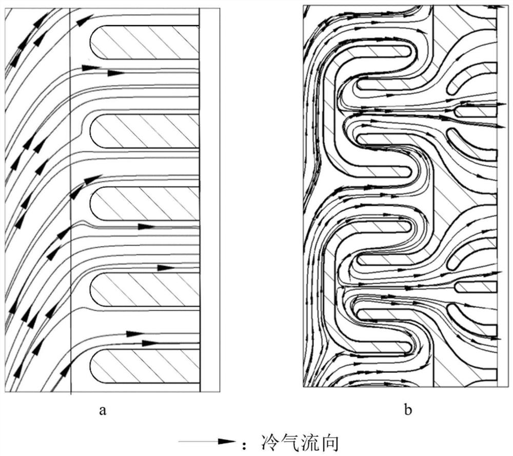
[0026] The hollow turbine blade 1 is provided with an inner cavity cold air channel 2 for the low temperature cooling gas to flow inside the blade to cool the blade. The trailing edge of the blade is evenly distributed with herringbone-shaped partition ribs 6 and C-shaped partition ribs 7 along the radial direction. A cold air separation channel 8 is formed between two adjacent C-shaped ribs and its width is D 1 = 2.4mm, the cold air flows downstream in this channel and is separated into two airflows that flow to the blade root and the blade tip respectively, and the first 180° rotation is performed in the two cold air rotation channels respectively, and the reverse flow in the direction of the inco...

Embodiment 2

[0029] The cooling structure of separation, lateral rotation and re-convergence provided by the present invention can be used not only on the trailing edge of the blade, but also on the leading edge of the blade, such as Figure 4 shown.

[0030] The hollow turbine blade 1 is evenly distributed with C-shaped ribs 7 and reversed C-shaped ribs 17 on the leading edge along the radial direction. .

[0031] A cold air separation channel 8 is formed between two adjacent front edge reverse C-shaped ribs 17 and its width is D 1 =2.4mm, the cold air flows downstream in this channel and is separated into two airflows that flow to the blade root and the blade tip respectively, and the first 180° rotation is performed in the two cold air rotation channels respectively, and the reverse flow in the direction of the incoming flow . Except for the two at the ends, two cold air circulation channels 9 are formed between each front edge reverse C-shaped rib 17 and two adjacent C-shaped ribs 7...


PUM


Abstract

The invention belongs to the technical field of aero-engine turbine cooling, and relates to a turbine blade separation, lateral rotation, and then converging cooling structure. The hollow turbine blade of the cooling structure is provided with an inner cavity cold air channel for low-temperature cooling gas to flow inside the blade. Cool down. The trailing edge of the blade is evenly distributed with herringbone-shaped partition ribs and C-shaped partition ribs along the radial direction. A cold air separation channel is formed between two adjacent C-shaped ribs and its width is D 1 , the cold air flows downstream in this channel and is separated into two airflows that flow to the blade root and the blade tip respectively, and the first 180° rotation is performed in the two cold air rotation channels respectively, and the reverse flow in the direction of the incoming flow. The cold air of the present invention needs to be turned several times before it can flow out through the trailing edge split, and its flow distance is increased by about 40% compared with the conventional structure, thereby improving the utilization rate of the cold air and reducing the temperature of the blade.

Description

technical field [0001] The invention belongs to the technical field of aero-engine turbine cooling, and relates to a turbine blade separation, lateral rotation, and then converging cooling structure. Background technique [0002] For aero-engines and gas turbines, increasing the temperature of the gas before the turbine can greatly improve the efficiency of the device, but because the ambient temperature of the gas is much higher than the current material's ability to withstand, it causes the cooling problem of the turbine blades. At present, the hollow design of turbine blades is generally adopted, and the enhanced convection heat transfer zone of the cooling gas inside the cooling gas is used to dissipate heat. At the same time, the blades have "larger internal heat exchange area", "lower cold air flow resistance", "higher heat exchange efficiency", "larger air film coverage area", "smaller damage to structural strength", etc. are designed for blade cooling. focus and goa...

Claims


Application Information

Patent Timeline
Patent Type & Authority Patents(China)
IPC IPC(8): F01D5/18
CPCF01D5/186F01D5/188
Inventor 吕东刘英实韦文涛张涛孔星傲孙一楠
Owner DALIAN UNIV OF TECH
Why Eureka
Try Eureka