
Defect detection method and device

A defect detection and defect point technology, which is applied in the direction of measuring devices, semiconductor/solid-state device testing/measurement, instruments, etc., can solve the problems of long time consumption and achieve the effect of reducing time consumption

Active Publication Date: 2019-12-10
北京施达优技术有限公司
View PDF6 Cites 0 Cited by
  • Summary
  • Abstract
  • Description
  • Claims
  • Application Information

AI Technical Summary

Problems solved by technology

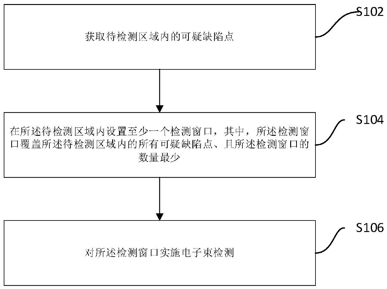
[0006] The main purpose of the present invention is to provide a defect detection method and device to solve the problem in the prior art that it takes a long time to detect suspicious defect points

Method used


Image

  • Defect detection method and device
  • Defect detection method and device
  • Defect detection method and device

Examples


Embodiment Construction

[0016] It should be noted that, in the case of no conflict, the embodiments of the present invention and the features in the embodiments can be combined with each other. The present invention will be described in detail below with reference to the accompanying drawings and examples.

[0017] In order to enable those skilled in the art to better understand the solutions of the present invention, the following will clearly and completely describe the technical solutions in the embodiments of the present invention in conjunction with the drawings in the embodiments of the present invention. Obviously, the described embodiments are only It is an embodiment of a part of the present invention, but not all embodiments. Based on the embodiments of the present invention, all other embodiments obtained by persons of ordinary skill in the art without making creative efforts shall fall within the protection scope of the present invention.

[0018] It should be noted that the terms "first...


PUM


Abstract

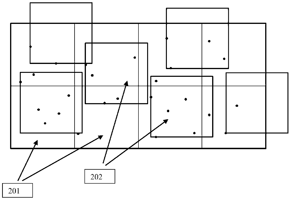
The invention provides a defect detection method and device. The method comprises the following steps of acquiring suspicious defect points in an area to be detected; arranging at least one detectionwindow in the area to be detected, wherein the detection windows cover all the suspicious defect points in the area to be detected, and the number of the detection windows is least; and carrying out electron beam detection on the detection windows. In the invention, the detection windows whose number is less than that of tiled detection windows are adopted; the small number of detection windows can cover all the suspicious defect points; the fewer the number of the detection windows is, the shorter the time consumed for detecting the defect points through electron beams is; a technical problemthat in the prior art, much time is consumed when the tiled detection windows are arranged is solved, and a technical scheme of reducing time consumption is achieved.

Description

technical field [0001] The invention relates to the field of semiconductors, in particular to a defect detection method and device. Background technique [0002] Large-scale integrated circuit manufacturing technology manufactures circuit structures on the surface of single crystal silicon wafers through etching and other technologies. However, as the chip manufacturing process continues to shrink, it becomes more difficult to detect defect points in the chip manufacturing process. Yield impact with wafer production is increasing. [0003] Electron beam inspection tool (Electron beam inspection tool), by focusing the electron beam to the surface of the object to be inspected (wafer in this patent), and collecting secondary electrons (secondary electrons) and backscattered electrons generated after the electron beam collides with the object to be inspected (backscattered electron), which converts the electrical signal into an image signal to obtain a microscopic image of the...

Claims


Application Information

Patent Timeline
Patent Type & Authority Applications(China)
IPC IPC(8): H01L21/66G01N23/204G01N23/2206G01N23/2251
CPCH01L22/12G01N23/204G01N23/2206G01N23/2251
Inventor 秦明侍乐媛高思阳
Owner 北京施达优技术有限公司
Learn More