A Switched Reluctance Generator Converter System

A switched reluctance and generator technology, which is applied to control generators, control generators through magnetic field changes, control systems, etc., can solve problems such as increasing the structure and control complexity of the system, reducing reliability, etc. Continuous voltage output regulation, the effect of wide voltage range

Active Publication Date: 2021-02-12
CHINA JILIANG UNIV
View PDF6 Cites 0 Cited by
  • Summary
  • Abstract
  • Description
  • Claims
  • Application Information

AI Technical Summary

Problems solved by technology

[0003] During the operation of the switched reluctance generator, before each phase winding sends out electric energy, it needs to absorb electric energy to store and excite its own winding. The excitation electric energy, especially the excitation voltage, greatly affects the excitation current of the phase winding and the output capacity of subsequent power generation. Therefore, The variable excitation voltage can be adjusted, especially to increase the adaptability of power generation output; on the other hand, the industry often uses battery packs as the excitation power supply, and the problem of battery charging occurs, especially when there are multiple batteries and they do not share the same ground. The charging system poses a challenge. If there are too many and too complicated charging systems, it will inevitably greatly increase the complexity of the structure and control of the entire system, as well as the cost, and reduce the reliability.

Method used


Image

  • A Switched Reluctance Generator Converter System

Examples


Embodiment Construction

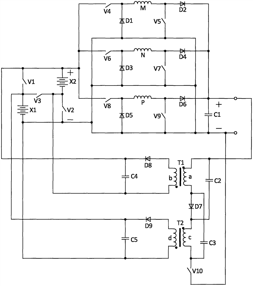
[0022] In this embodiment, a switched reluctance generator converter system with wide range excitation power generation and automatic double charging, the circuit structure of the converter system is as follows figure 1As shown, it consists of the first storage battery X1, the second storage battery X2, the first switching tube V1, the second switching tube V2, the third switching tube V3, the fourth switching tube V4, the fifth switching tube V5, and the sixth switching tube V6 , the seventh switching tube V7, the eighth switching tube V8, the ninth switching tube V9, the tenth switching tube V10, the first phase winding M, the second phase winding N, the third phase winding P, the first diode D1, The second diode D2, the third diode D3, the fourth diode D4, the fifth diode D5, the sixth diode D6, the seventh diode D7, the eighth diode D8, the Nine diodes D9, the first capacitor C1, the second capacitor C2, the third capacitor C3, the fourth capacitor C4, the fifth capacitor ...


PUM


Abstract

A switched reluctance generator conversion system, its structure is composed of two batteries, ten switch tubes, nine diodes, five capacitors, three-phase windings, two transformers, two batteries and three switch tubes can be high and low The excitation power supply with adjustable excitation output voltage in a low and wide range greatly improves the system adaptability and power generation capacity; directly relying on the simple conversion circuit of each phase winding, and with the support of the excitation power supply, it solves the problem that the output power generation voltage can be generated in a wide range The problem of adjusting the output, especially when the output is high voltage, saves the subsequent step-up link; for the two batteries that do not share the same ground in the excitation power supply, the present invention only uses one switch tube to realize the automatic isolation charging of the two batteries that do not share the same ground , improve the sustainability and reliability of the system, and simplify the structure and control; the invention is suitable for application in switched reluctance generator systems with various power inputs and various output loads.

Description

technical field [0001] The invention relates to the field of switched reluctance motor systems, in particular to a switched reluctance generator converter system and a control method thereof, which have wide-range excitation voltage input, wide-range power generation voltage output, single input and double output, and automatically charge two excitation storage batteries at the same time . Background technique [0002] The switched reluctance motor has a simple and firm structure, low cost and high reliability, and has broad application prospects as a generator. [0003] During the operation of the switched reluctance generator, before each phase winding sends out electric energy, it needs to absorb electric energy to store and excite its own winding. The excitation electric energy, especially the excitation voltage, greatly affects the excitation current of the phase winding and the output capacity of subsequent power generation. Therefore, The variable excitation voltage ...

Claims


Application Information

Patent Timeline
Patent Type & Authority Patents(China)
IPC IPC(8): H02P9/30H02P9/38H02P9/00H02J7/34H02J7/00
CPCH02J7/345H02P9/00H02P9/30H02P9/38
Inventor 孙冠群李璟翁馨
Owner CHINA JILIANG UNIV
Why Eureka
Try Eureka