Quick binding tourniquet for middle-aged and elderly people

A technology for middle-aged and elderly people and a pressure cuff, which is applied to the field of fast tying cuff for middle-aged and elderly people, can solve problems such as skin pulling, and achieve the effect of protecting the hand.

Active Publication Date: 2019-12-13
JILIN UNIV FIRST HOSPITAL
5 Cites 0 Cited by

AI-Extracted Technical Summary

Problems solved by technology

[0005] The purpose of the present invention is to solve the problems of skin tearing caused by the soft cortex of middle-aged and eld...

Abstract

The invention discloses a rapid binding tourniquet for middle-aged and elderly people. According to the invention, a telescopic bubble is arranged on the outer side wall of a pipeline, an adjusting ring is movably installed in a channel, an external sliding hole is formed in the portion, connected with the telescopic bubble, of the pipeline, a reset spring is elastically connected to the middle ofthe sliding needle, the bottom end of an extension spring is fixedly connected to one end of an air pipe, and an outer port of the air pipe penetrates through the interior of the channel and is fixedly connected with the channel. The part of the air pipe on the inner side of the pipeline returns to an original shape after losing a tightening state, at the moment, sufficient gas is sucked into theair pipe at the moment of relaxation, after a pull rope spring loses the stretching force, the side end of the pull rope spring penetrates through a wrapped miniature expansion body and also sucks part of gas in the air pipe, the expansion body is extruded by the extension spring after bulging, the telescopic bubble is supported outwards and bounces off the wrist of a patient instantly, and the outer pipeline of the tourniquet can be prevented from clamping the outer epidermis of the wrist of the patient.

Application Domain

Technology Topic

Image

  • Quick binding tourniquet for middle-aged and elderly people
  • Quick binding tourniquet for middle-aged and elderly people
  • Quick binding tourniquet for middle-aged and elderly people

Examples

  • Experimental program(1)

Example Embodiment

[0027] In order to make it easy to understand the technical means, creative features, objectives and effects achieved by the present invention, the preferred embodiments of the present invention will be further described below in conjunction with the description of specific embodiments and drawings.
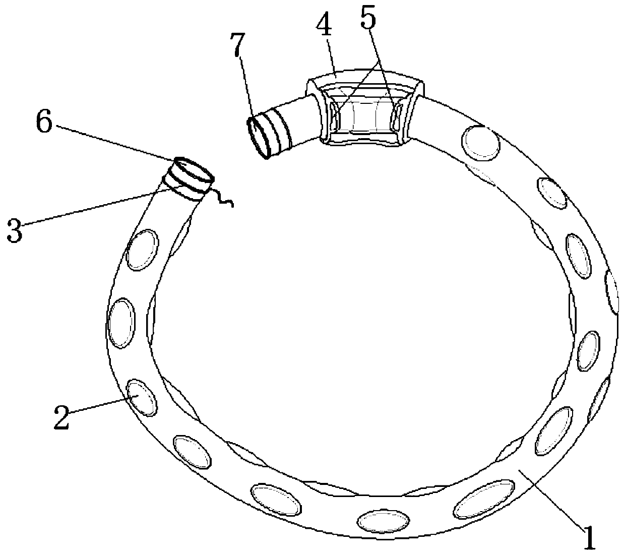
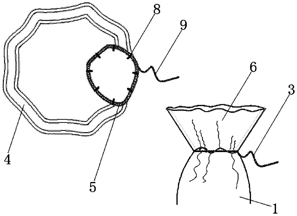
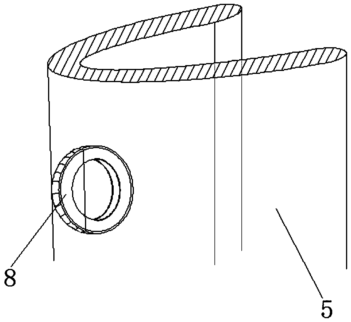
[0028] Such as Figure 1 to Figure 6 As shown, the present invention provides a fast lashing cuff for middle-aged and elderly people. One end of the pipe 1 is fixedly installed with an interface 6; the other end of the pipe 1 is fixedly connected with an interface 2 7; the inner ring of the interface 6 is penetrated with a movable rope 3. One end of the pipe 1 near the interface two 7 penetrates through the central axis of the lock ring 4, the side end of the lock ring 4 is provided with a channel 5, the inner side of the channel 5 is movably installed with a rolling wheel 8, and the outer side wall of the interface 6 The middle part penetrates the middle part of the stop ring 10, the inner wall of the pipe 1 is fixedly connected with a movable block 12, the inner side of the movable block 12 is elastically connected to the outer side of the pleated inner wall 13, and the inner side of the pleated inner wall 13 is elastically connected to the sliding needle 14. The outer end of the sliding pin 14 is movably clamped to the top end of the tension spring 15;
[0029] Wherein, a telescopic bubble 2 is provided on the outer side wall of the pipe 1. When the pipe 1 is pulled to a tight state during use, the telescopic bubble 2 is in a deflated state;
[0030] Among them, an adjustment ring is movably installed inside the channel 5, and the adjustment ring is movably connected to the inner end of the traction rope 9. When the medical staff fixes the outer side of the pipeline 1 to the patient's wrist, the interface at this time is in the state of 6 It is tightened. After placing it in the channel 5 to relax the movable rope, the interface 6 returns to its original state. Since the tightness of the pipeline 1 needs to be fixed, the adjustment ring needs to be adjusted to fix the interface 1. 6 locations;
[0031] Among them, the part where the pipe 1 and the telescopic bubble 2 are connected is provided with an external sliding hole 11, and the trachea inside the pipe 1 connected to the inner side of the channel 5 is restored to its original shape after losing the stretched and tight state. The inside of the trachea will inhale a sufficient amount of gas at the moment of relaxation. After the drawstring spring 15 loses the strength of being stretched, the micro expansion body wrapped by its side end penetrates through the external sliding hole 11 and sucks a part of the expansion body inside the trachea. After the expansion body is swollen, it is squeezed by the tension spring 15 so that the telescopic bubble 2 is propped up and bounces away from the patient's wrist in an instant, which can prevent the cuff tube 1 from getting stuck in the patient's wrist. epidermis;
[0032] Among them, the movable block 12 is composed of the inner ends of a plurality of movable small plates movably connected, and the pleated inner wall 13 can drive the movable plate 12 to rotate during the movement;
[0033] Among them, the pleated inner wall 13 is composed of a plurality of movable small soft plates elastically connected. When the pipe 1 is stretched to a tight state, the pleated inner wall 13 can control the amount of gas in and out by the tightness of the pipe 1;
[0034] Wherein, the middle part of the sliding needle 14 is elastically connected with a return spring, and the sliding needle 14 can be restored to its original state by the return spring after losing its restriction;
[0035] Wherein, the bottom end of the tension spring 15 is fixedly connected to one end of the trachea, the other end of the trachea penetrates the inside of the pipe 1 and extends to the outer end of the pipe 1, and the outer port of the trachea penetrates through the inside of the channel 5 and is fixedly connected to it. The side of the extension spring 15 is wrapped with an expansion body. When the pipeline 1 is no longer in a tight state, the extension spring 15 is reset, and a certain amount of gas is sucked in the inside of the trachea and transferred to the inside of the expansion body to make it bulge.
[0036] Among them, the flexible bubble 2 is made of soft plastic material.
[0037] The working principle and process of the present invention:
[0038] In the present invention, the user can wrap the middle part of the tube 1 of the cuff around the patient's wrist, and tighten the movable rope 3 at the port of the tube 1 near the port 6 to the outside. Made of elastic plastic material. Therefore, after tightening the port 6 and inserting it into the channel 5 and passing through the inside of the channel 5, the plastic rubber pipe at the port 6 will return to its original shape due to its own elasticity, and the port 6 is in the channel 5 When the inside is stuck, the rubber material of interface 6 makes itself propped to the outside at the bayonet of channel 5. The outer side of the lock ring 4 is close to the outer side of the channel 5 and a button is movably installed, and the inner side of the button penetrates the lock ring 4 The side wall to the inside of the channel 5 is elastically connected to the roller in the direction of the slope, which can be used to limit the position of the port 6. When the user pulls the port 6 to the right, a trachea connected to the inner wall of the channel 5 It leads to the inside of port 6, so when port 6 is passively moving to the right end of channel 5, the middle of the trachea is exposed at the port of the internal vent of port 6, and the user hooks the exposed trachea with his fingers. One end is connected to the bottom end of the extension spring 15 inside the pipe 1, so when the user pulls the outer port of the port 6 to move outward, when the inner end of the extension spring 15 is pulled toward a line, the sliding needle When the position of 14 is adjusted to be nearly parallel to the pleated inner wall 13, the outer wall of the pleated inner wall 13 will not bulge at this time. After use, the user can press the movable button on the outer wall of the lock ring 4 , Pull out the tube 1 from the inside of the channel 5. At this time, the trachea inside the tube 1 connected to the inner side of the channel 5 loses the stretched and tight state and returns to its original state. At this time, the trachea will relax Sufficient gas is sucked in at the moment, and after the drawstring spring 15 loses the strength of being stretched, the miniature expansion body wrapped by its side end also sucks in part of the gas inside the trachea. After the expansion body bulges, it is subjected to the tension spring again. The squeezing of 15 makes the telescopic bubble 2 prop up outwards and instantly bounces away from the patient's wrist, which can prevent the outer tube of the cuff from jamming the outer skin of the patient's wrist;
[0039] Since the pipe 1 is made of soft plastic rubber material, in order to avoid damage caused by excessive friction when passing through the channel 5, a rolling wheel 8 is provided inside the channel 5, and the rolling wheel 8 is tightly located on the outer side wall of the pipe 1 When fitting and rolling, it can facilitate the pipe 1 to slide inside the channel 5 to avoid the outer wall of the pipe 1 from being damaged by friction. After the interface 6 is successfully connected to the channel 5, the user can adjust it to a suitable position and then pull it. The traction rope 9 is contracted, and the movable buckle inside the channel 5 is engaged with the limit ring 10 to tighten the tight state of the cuff.
[0040] Using the technical solutions of the present invention, or those skilled in the art under the inspiration of the technical solutions of the present invention, design similar technical solutions, and achieving the above technical effects fall within the protection scope of the present invention.

PUM

no PUM

Description & Claims & Application Information

We can also present the details of the Description, Claims and Application information to help users get a comprehensive understanding of the technical details of the patent, such as background art, summary of invention, brief description of drawings, description of embodiments, and other original content. On the other hand, users can also determine the specific scope of protection of the technology through the list of claims; as well as understand the changes in the life cycle of the technology with the presentation of the patent timeline. Login to view more.

Similar technology patents

Mining jackdrill handle with shock absorption function

ActiveCN109015538AAvoid hand injuryHand protectionMetal-working hand toolsEngineering
Owner:平利县篮泰重晶石工贸有限公司

Green vegetable disinfecting equipment

PendingCN109315801AEasy to clean thoroughlyHand protectionFood treatmentGreen VegetableThreaded rod
Owner:KEPURUITIANJIN KITCHEN EQUIP CO LTD

Simple cable stripper

Owner:STATE GRID TIANJIN ELECTRIC POWER +1

Filter unit for kitchen sink

InactiveCN107447824AHand protectionAvoid the influence of excessive water pressure and make it difficult to open the plugDomestic plumbingEngineeringMotherboard
Owner:江门市宝佳厨卫有限公司

Classification and recommendation of technical efficacy words

  • Hand protection

Packaging scissors

InactiveUS20100293793A1Hand protectionMetal working apparatusKnife blades
Owner:UNDERHILL RODNEY

Strap and electronic device

ActiveUS20150177791A1Significant burdenHand protectionTravelling carriersHoldersEngineeringMechanical engineering
Owner:PANASONIC INTELLECTUAL PROPERTY MANAGEMENT CO LTD

Mining jackdrill handle with shock absorption function

ActiveCN109015538AAvoid hand injuryHand protectionMetal-working hand toolsEngineering
Owner:平利县篮泰重晶石工贸有限公司

Green vegetable disinfecting equipment

PendingCN109315801AEasy to clean thoroughlyHand protectionFood treatmentGreen VegetableThreaded rod
Owner:KEPURUITIANJIN KITCHEN EQUIP CO LTD

Simple cable stripper

Owner:STATE GRID TIANJIN ELECTRIC POWER +1

People also interested in

Why Eureka
Try Eureka