Continuous garbage treatment device

A waste disposal device, continuous technology, applied in grain processing, presses, manufacturing tools, etc., can solve problems such as low work efficiency

Active Publication Date: 2019-12-13
泓欣环境集团有限公司
View PDF10 Cites 2 Cited by
  • Summary
  • Abstract
  • Description
  • Claims
  • Application Information

AI Technical Summary

Problems solved by technology

[0002] Garbage treatment requires compaction of the garbage, and there is generally only one compaction chamber in the prior art, so the compaction process needs to wait for the compaction chamber to be compacted and discharged before the second compaction operation can be performed. The efficiency is low, so it is necessary to install a continuous waste treatment device that can compact the waste efficiently

Method used


Image

  • Continuous garbage treatment device
  • Continuous garbage treatment device
  • Continuous garbage treatment device

Examples


Embodiment 1

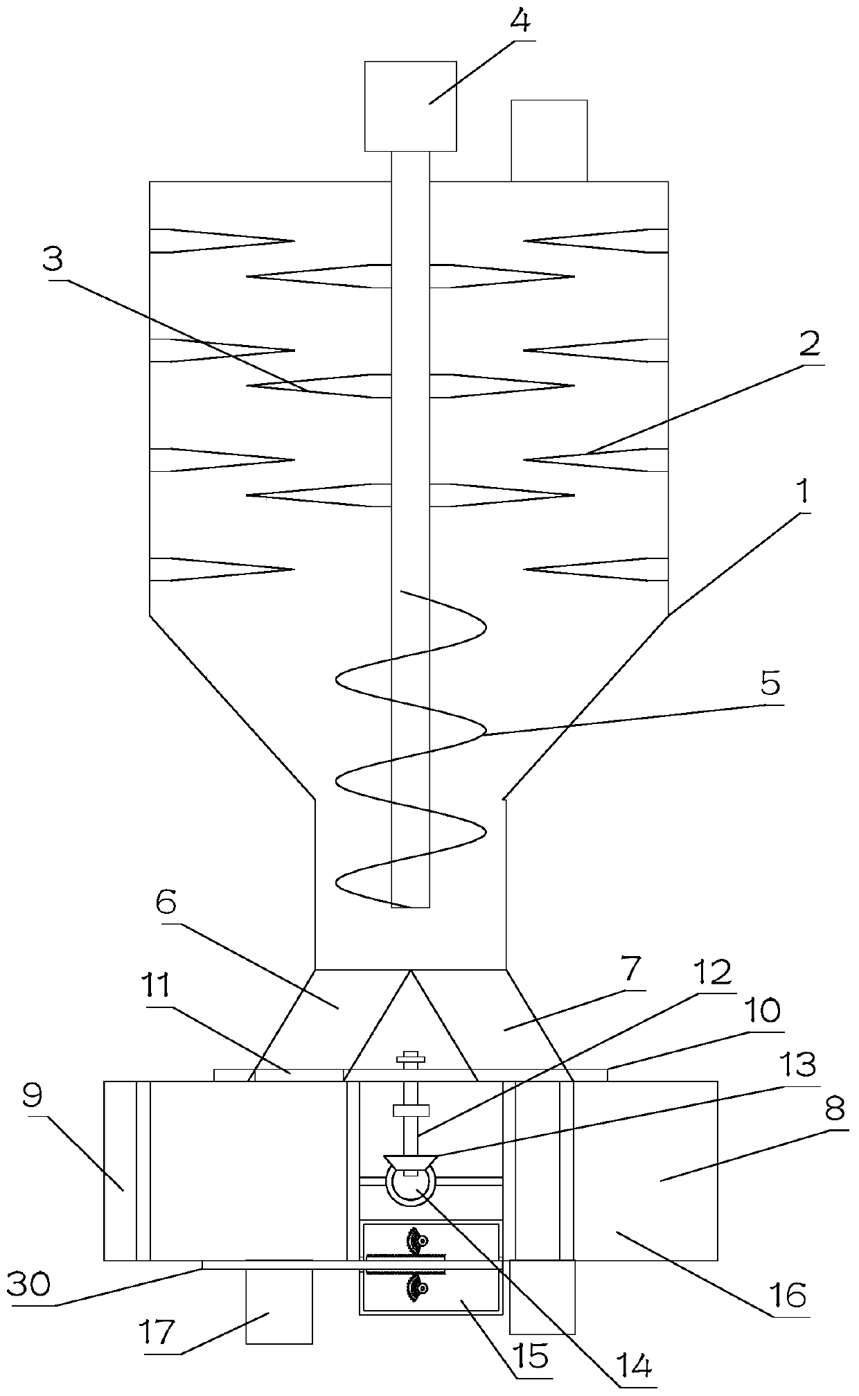
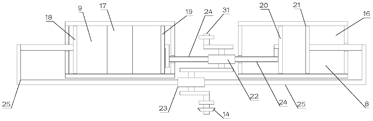
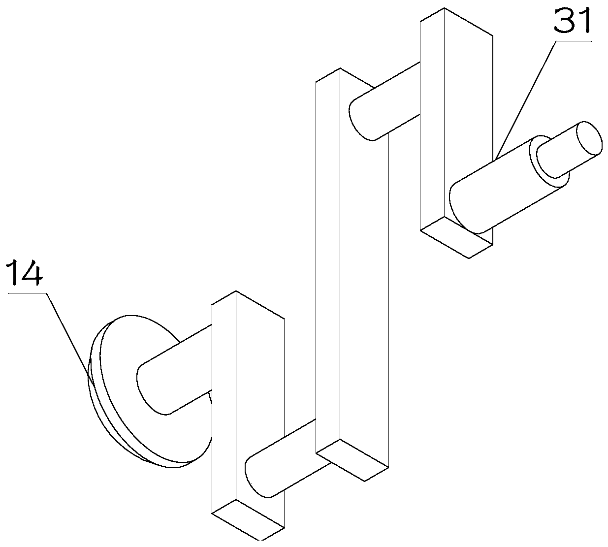
[0022] See Figure 1~3 , In the first embodiment of the present invention, a continuous garbage disposal device includes a crushing body 1, and the bottom outlet of the crushing body 1 is provided with an A conveying pipe 6 and a B conveying pipe 7 communicating with it. A ram plate 10 is arranged at the bottom of A feed pipe 6 and B feed pipe 7, and A ram plate 10 is provided with a through hole 11 for controlling the on and off of A feed pipe 6 and B feed pipe 7. The outlets of the A feed pipe 6 and the B feed pipe 7 are respectively communicated with the B compacting cavity 9 and the A compacting cavity 8 inside the compression assembly 16; the A gate plate 10 is rotatably mounted on the compression assembly 16; A compacting cavity 8 is provided with a C pressure plate 20 and a D pressure plate 21 that are matched with each other, and the B compacting cavity 9 is provided with a mutually matched A pressure plate 18 and a B pressure plate 19, and the crankshaft 31 is rotatably...

Embodiment 2

[0025] See Figure 1~5 The main difference between this embodiment 2 and embodiment 1 is that the crushing body 1 is provided with a B rotating shaft, the B rotating shaft is fixedly provided with B crushing teeth 3, and the inner wall of the crushing body 1 is provided with a B crushing tooth 3 Cooperate with broken A crushing teeth 2; the upper part of the B rotating shaft is fixedly installed at the output end of A motor 4; setting A crushing teeth 2 and B crushing teeth 3 is convenient for crushing garbage.

[0026] The crushing body 1 is provided with a feeding port.

[0027] A conveyor auger 5 is fixedly arranged at the bottom of the B rotating shaft, and the conveyor auger 5 is arranged to facilitate the squeezing of the garbage after the crushing, and ensure the continuous discharge of the garbage.

[0028] The A shaft 12 is fixedly installed in the middle position of the A gate 10, the A shaft 12 is rotatably mounted on the compression assembly 16, and the A bevel gear 13 i...


PUM


Abstract

The invention discloses a continuous garbage treatment device, and relates to the technical field of environmental protection equipment. The continuous garbage treatment device comprises a crushing main body, wherein a conveying pipe A and a conveying pipe B communicating with the crushing main body are arranged at an outlet at the bottom of the crushing main body; a self-rotating gate plate A isarranged at the bottoms of the conveying pipe A and the conveying pipe B; outlets of the conveying pipe A and the conveying pipe B respectively communicate with a compaction cavity B and a compactioncavity A inside a compression assembly; the gate plate A is rotatably mounted on the compression assembly; a pressing plate C and a pressing plate D which are mutually matched are arranged in the compaction cavity A; a pressing plate A and a pressing plate B which are mutually matched are arranged in the compaction cavity B; a crankshaft is rotatably mounted on the compression assembly; two connecting rod journals are arranged on the crankshaft; a rotating block B and a rotating block A are respectively and rotatably mounted on the two connecting rod journals; two connecting rods A are respectively mounted on the two sides of the rotating block A; and the other ends of the two connecting rods A are respectively hinged to the pressing plate A and the pressing plate D. By means of the continuous garbage treatment device, the continuous high-efficiency compaction of garbage is achieved.

Description

Technical field [0001] The invention relates to the technical field of environmental protection equipment, in particular to a continuous garbage treatment device. Background technique [0002] Garbage treatment requires a compaction operation for the garbage, and there is generally only one compaction chamber in the prior art. Therefore, the compaction process needs to be completed after the compaction chamber is compacted and discharged before the second compaction operation can be performed. This kind of operation works The efficiency is low, so it is necessary to install a continuous garbage disposal device that can efficiently compact the garbage. Summary of the invention [0003] The purpose of the present invention is to provide a continuous garbage disposal device to solve the above-mentioned background art problems. [0004] In order to achieve the above objectives, the present invention provides the following technical solutions: [0005] A continuous garbage disposal devic...

Claims


Application Information

Patent Timeline
Patent Type & Authority Applications(China)
IPC IPC(8): B02C18/10B30B9/30B30B15/32
CPCB02C18/0092B02C18/10B02C2201/06B30B9/3014B30B9/306B30B9/3092
Inventor 喻光明
Owner 泓欣环境集团有限公司
Why Eureka
Try Eureka