
Multi-flow channel inkjet device

An inkjet device and multi-channel technology, which is applied in printing and other directions, can solve the problems that single-channel injection devices cannot meet market demand, affect work efficiency, and have long downtime, so as to realize automatic operation, improve production efficiency, and improve production efficiency. Use simple effects

Inactive Publication Date: 2019-12-13
上海奥色智能科技有限公司
View PDF7 Cites 3 Cited by
  • Summary
  • Abstract
  • Description
  • Claims
  • Application Information

AI Technical Summary

Problems solved by technology

[0002] Existing liquid injection devices generally use single-channel jetting ink, glue or special solvent, but the ink, glue or special solvent contains an appropriate amount of polymer to increase its adhesion or fast drying ability, and the nozzle ejection port of the device The diameter is generally 0.1mm ~ 0.25mm. Due to the long downtime of the jet nozzle during work, it is easy to cause the jet liquid to dry up and block the nozzle or accumulate around the nozzle; the traditional cleaning mode can only use manual surface cleaning around the nozzle by stopping the operation. Objects or disassemble the spray device to clean the inside and outside of the nozzle
This kind of device is not easy to operate, and it takes a lot of working time to clean the clogged nozzles in actual production, which affects work efficiency
On the other hand, in the actual production process of enterprises, dual-channel or multi-channel is required to configure different-color injection media, and single-channel injection devices cannot meet market demand. Therefore, there is an urgent need for a dual-channel or multi-channel in the market. inkjet device

Method used


Image

  • Multi-flow channel inkjet device
  • Multi-flow channel inkjet device
  • Multi-flow channel inkjet device

Examples


Embodiment Construction

[0040] The present invention will be described in detail below in conjunction with specific embodiments. The following examples will help those skilled in the art to further understand the present invention, but do not limit the present invention in any form. It should be noted that those skilled in the art can make several changes and improvements without departing from the concept of the present invention. These all belong to the protection scope of the present invention.

[0041] In describing the present invention, it is to be understood that the terms "upper", "lower", "front", "rear", "left", "right", "vertical", "horizontal", "top", The orientation or positional relationship indicated by "bottom", "inner", "outer", etc. is based on the orientation or positional relationship shown in the drawings, and is only for the convenience of describing the present invention and simplifying the description, rather than indicating or implying the referred device Or elements must h...


PUM


Abstract

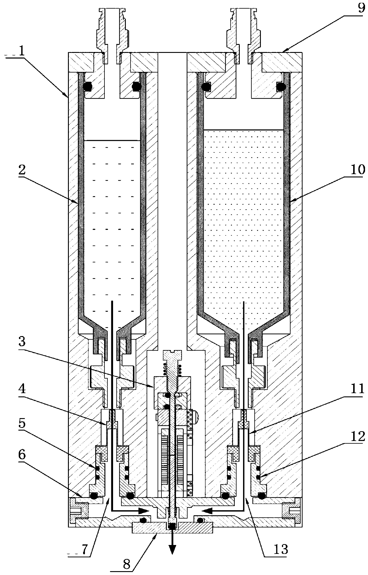
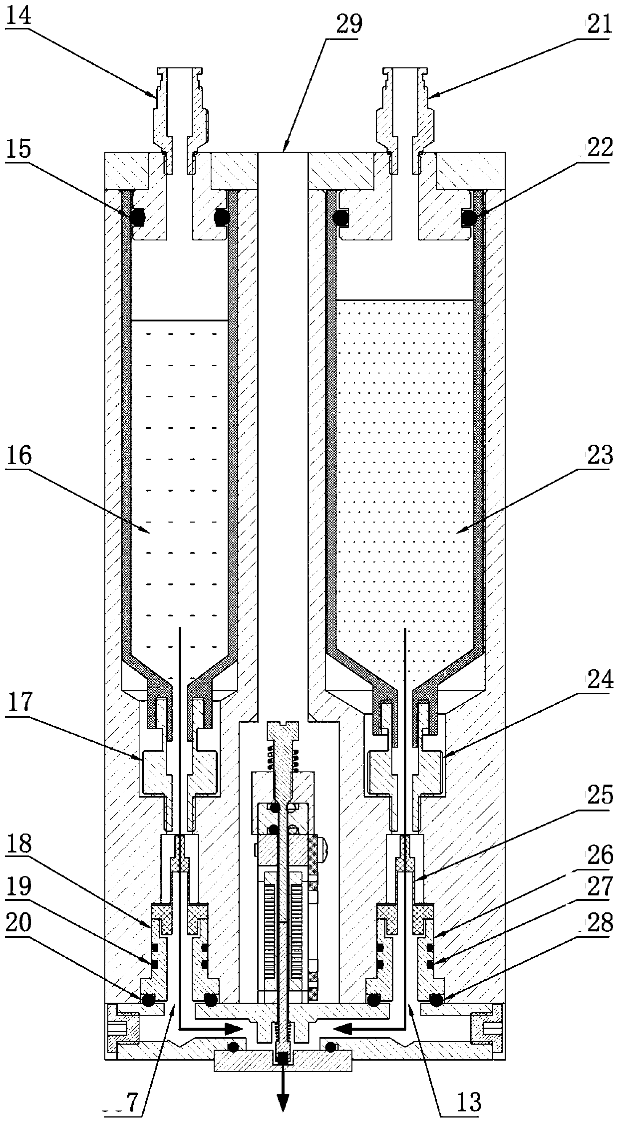
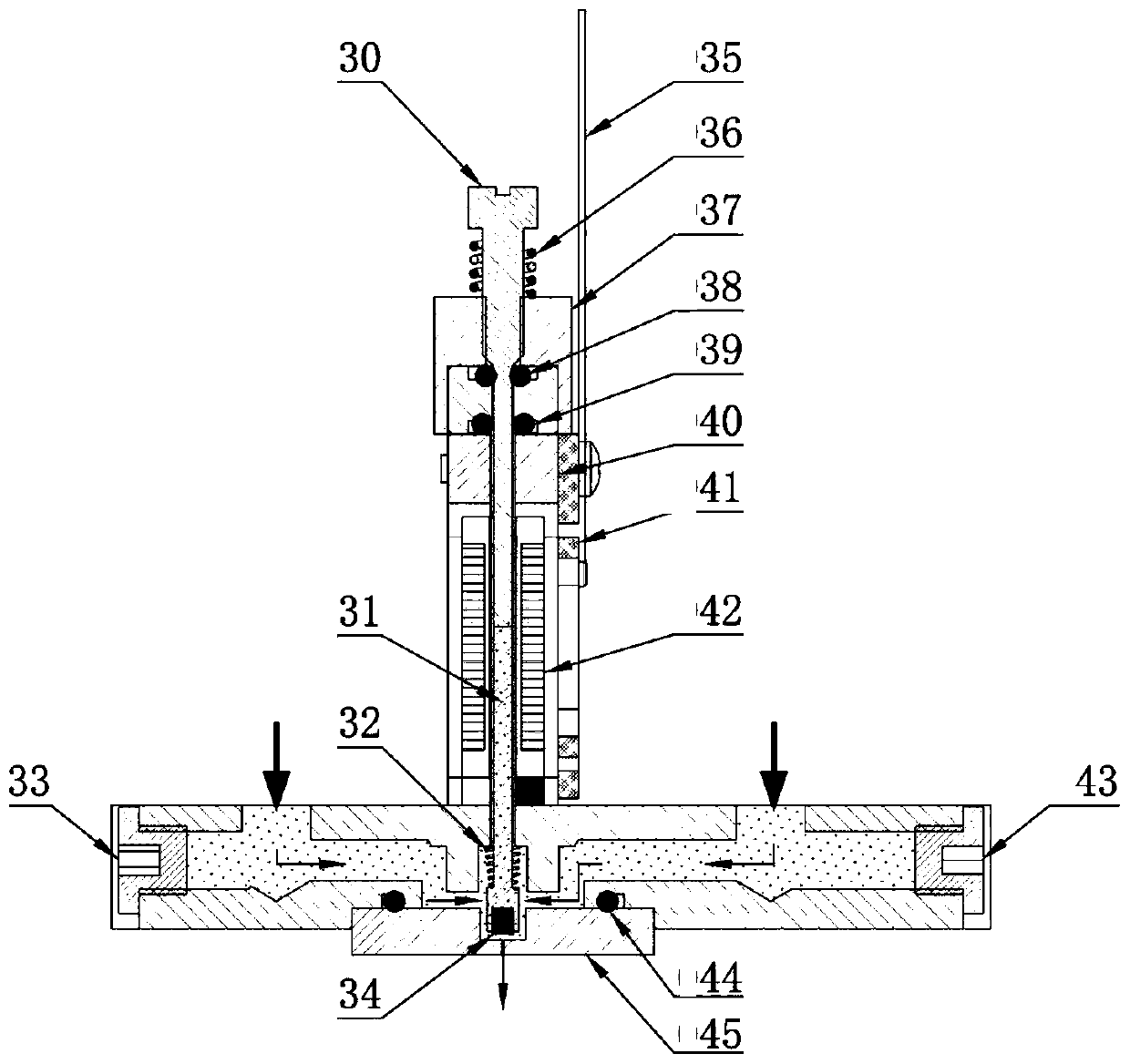
The invention provides a multi-flow channel inkjet device. The device comprises an integrated cavity, an air inlet assembly, an electromagnet assembly, an anti-serial ink valve assembly, a sealing assembly, a bus plate, a nozzle assembly and a plurality of container assemblies, wherein the plurality of container assemblies are arranged in the integrated cavity, inlets of the plurality of containerassemblies is connected with the air inlet assembly, outlets of the plurality of container assemblies is connected with the anti-serial ink valve assembly and is connected to the bus plate, a plurality of flow channels are arranged in the bus plate and are in one-to-one correspondence with the outlets of the plurality of container assemblies, the bus plate is connected with the nozzle assembly, the plurality of flow channels converge to a nozzle of the nozzle assembly, and an electromagnet assembly controls opening and closing of the nozzle. According to the device, the plurality of flow channels are arranged, the anti-serial ink valve assembly is arranged, so that the flow channels are free to switch during work and does not interfere with each other, the device can switch to a cleaningagent flow channel to work automatically, the nozzle can be automatically cleaned without disassembling the nozzle, and the nozzle can work smoothly, automatic operation can be realized, and operation, maintenance and maintenance time can be greatly saved.

Description

technical field [0001] The present invention relates to the technical field of liquid ejection devices, in particular, to a multi-channel inkjet device. Background technique [0002] Existing liquid injection devices generally use single-channel jetting ink, glue or special solvent, but the ink, glue or special solvent contains an appropriate amount of polymer to increase its adhesion or fast drying ability, and the nozzle ejection port of the device The diameter is generally 0.1mm ~ 0.25mm. Due to the long downtime of the jet nozzle during work, it is easy to cause the jet liquid to dry up and block the nozzle or accumulate around the nozzle; the traditional cleaning mode can only use manual surface cleaning around the nozzle by stopping the operation. Objects or disassemble the spray device to clean the inside and outside of the nozzle. This kind of device is inconvenient to operate, and takes up a large amount of working hours in actual production to clean up clogged noz...

Claims


Application Information

Patent Timeline
Patent Type & Authority Applications(China)
IPC IPC(8): B41J2/01B41J2/135B41J2/14B41J2/165
CPCB41J2/01B41J2/135B41J2/14B41J2/165B41J2/1652B41J2/16517B41J2/16552B41J2002/16573B41J2/16502
Inventor 李永年朱松李刊王鹏飞
Owner 上海奥色智能科技有限公司
Learn More