
Cubic star catapult

A catapult and cube technology, which is applied to aircraft, launch systems, and aerospace vehicles, etc., can solve problems such as lack of feedback information, poor versatility, and easy encounters.

Inactive Publication Date: 2019-12-13
陕西智星空间科技有限公司
View PDF7 Cites 2 Cited by
  • Summary
  • Abstract
  • Description
  • Claims
  • Application Information

AI Technical Summary

Problems solved by technology

[0002] The separation of traditional satellites and launch vehicles often adopts the separation method of tape and explosive bolts. This separation technology is relatively mature and is also widely used on large satellites. However, the fire attack device may produce fine particles at the moment of explosion. These fine particles After entering the satellite, such as optical lenses, etc., will cause great damage to the satellite's components. In addition, the explosive impact of the explosive bolt may affect the release of the cubesat. The current release of the cubesat below 12U usually uses a special The catapult is used to realize the in-orbit release of the satellite, and the versatility is extremely poor. In addition, the 12U catapult is mainly imported or the release method is the same as that of the small satellite, which is extremely wasteful of resources. The current 6U CubeSat catapult (POD) It can realize the connection with the rocket and the separation of small satellites. One end of the POD is equipped with a cylindrical spring, and the other end is a rotatable end cover with a torsion spring at the root. After the cover is released by the upper release device, it will rotate and open under the action of the torsion spring. The energy storage element slides out along the linear guide rail under the action of the cylindrical spring. The existing catapults generally have the following problems: At present, the versatility of the CubeSat catapult is relatively poor, and no suitable catapult device can be found after the Cube is developed. , greatly delaying its development process; the rotating end cover of the catapult will rebound due to inertia after being opened under the action of the torsion spring, and it is easy to touch and damage the sliding cube star; there is a lack of sufficient feedback information, including whether the rotating end cover is unfolded , whether the rotating end cover is unfolded in place, whether the spring is released in place, etc., are used to judge whether the cube star is ejected successfully; most of the locking mechanisms of the rotating end cover adopt the principle of solenoid valve or tension rope, and there are many accessory parts, and the structure is relatively complex, low reliability

Method used


Image

  • Cubic star catapult
  • Cubic star catapult
  • Cubic star catapult

Examples


Embodiment Construction

[0024] The following will clearly and completely describe the technical solutions in the embodiments of the present invention with reference to the accompanying drawings in the embodiments of the present invention. Obviously, the described embodiments are only some, not all, embodiments of the present invention. Based on the embodiments of the present invention, all other embodiments obtained by persons of ordinary skill in the art without making creative efforts belong to the protection scope of the present invention.

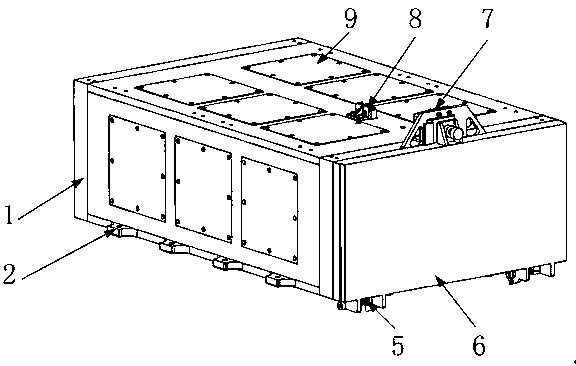
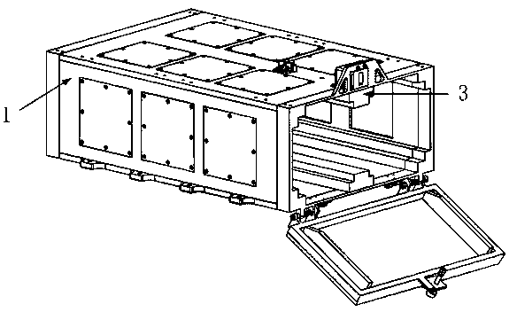
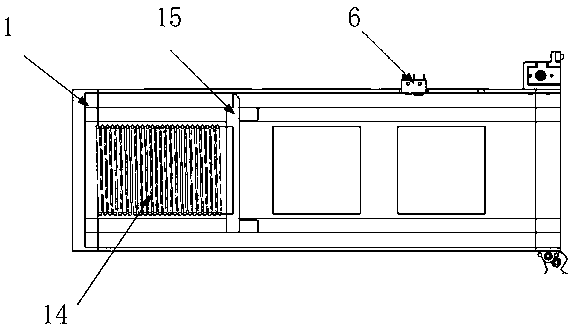
[0025] The present invention provides such Figure 1-6 As shown, in order to achieve the above purpose, the present invention provides the following technical solutions: including a main body shell 1, the outer surface of the lower end of the main body shell 1 is fixedly installed with an installation interface 2, and the outer surface of the lower end of the main body shell 1 is installed with a lock that is deployed in place. Component 3 and the feedback com...


PUM


Abstract

The invention discloses a cubic star catapult. The cubic star catapult comprises a main body outer shell; a mounting joint is fixedly mounted on the outer surface of the lower end of the main body outer shell; an unfolding in-place locking module and an unfolding in-place feedback module are mounted on the outer surface of the lower end of the main body outer shell; a torsion spring is fixedly mounted on the outer surface of one side of the main body outer shell; a rotating end cover is arranged on the outer surface of one side of the main body outer shell; and a locking release mechanism anda first micro switch are fixedly mounted on the outer surface of the upper end of the main body outer shell. The locking release mechanism is used for relieving constraint of the rotating end cover; the rotating end cover is unfolded under the effect of the torsion spring; cubic stars stored in the main body outer shell outwards slide along a linear chute guide rail under the effect of a launchingmechanism; in the sliding process, the rotating end cover is rotated by a certain angle for locking; and in the whole unfolding process, rotating end cover unfolding beginning, rotating end cover unfolding in-place and spring release in-place signals are returned back to a rocket to guarantee successful separation of the cubic stars from the catapult.

Description

technical field [0001] The invention relates to the field of catapults, in particular to a cube star catapult. Background technique [0002] The separation of traditional satellites and launch vehicles often adopts the separation method of tape and explosive bolts. This separation technology is relatively mature and is also widely used on large satellites. However, the fire attack device may produce fine particles at the moment of explosion. These fine particles After entering the satellite, such as optical lenses, etc., will cause great damage to the satellite's components. In addition, the explosive impact of the explosive bolt may affect the release of the cubesat. The current release of the cubesat below 12U usually uses a special The catapult is used to realize the in-orbit release of the satellite, and the versatility is extremely poor. In addition, the 12U catapult is mainly imported or the release method is the same as that of the small satellite, which is extremely ...

Claims


Application Information

Patent Timeline
IPC IPC(8): B64G1/00
CPCB64G1/005
Inventor 和向前刘丽坤马帅领杨益谦
Owner 陕西智星空间科技有限公司
Learn More