Movable multi-pump nozzle structure applied to air-jet loom

An air-jet loom and movable technology, which is applied in the field of textile processing, can solve the problems of inconvenient installation and flexible maintenance, inconvenience of flexible use of a single loom, occupying a large production space, etc. Convenient daily maintenance and flexible use, the effect of reducing the impact of vibration

Inactive Publication Date: 2019-12-13
CHANGLE LIZHI IND DESIGN CO LTD
View PDF1 Cites 1 Cited by
  • Summary
  • Abstract
  • Description
  • Claims
  • Application Information

AI Technical Summary

Problems solved by technology

[0003] However, during the use of existing air-jet looms, multiple looms are generally directly supplied with air through the air supply station, which is not only inconvenient for the flexible use of a single loom, but the external air supply mechanism, bobbin frame and weft feeder, etc. Both need to occupy a large production space, and it is not convenient to go online and maintain when the multi-weft nozzle is used. At the same time, when the multi-nozzle structure is used, the yarn lead is easily affected by vibration and weft insertion. The main nozzle device of the air-jet loom suppresses the vibration of the main nozzle through a certain fixed nozzle holder, but this structure only plays a restraining role, and the yarn itself will still be affected by a certain vibration, and the additional fixed nozzle holder will affect To the overall structural flexibility, it is not convenient for flexible inspection and maintenance of the device, which affects the normal use of the device

Method used


Image

  • Movable multi-pump nozzle structure applied to air-jet loom
  • Movable multi-pump nozzle structure applied to air-jet loom
  • Movable multi-pump nozzle structure applied to air-jet loom

Examples


Embodiment Construction

[0026] The following will clearly and completely describe the technical solutions in the embodiments of the present invention with reference to the accompanying drawings in the embodiments of the present invention. Obviously, the described embodiments are only some, not all, embodiments of the present invention. Based on the embodiments of the present invention, all other embodiments obtained by persons of ordinary skill in the art without making creative efforts belong to the protection scope of the present invention.

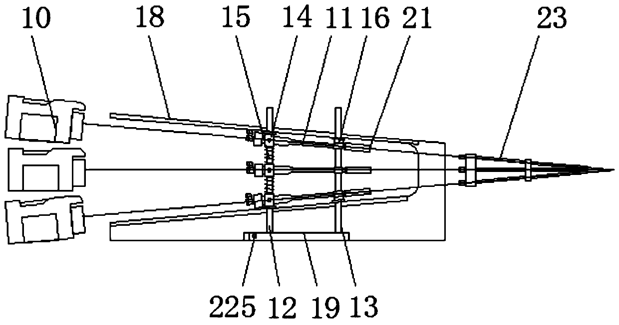
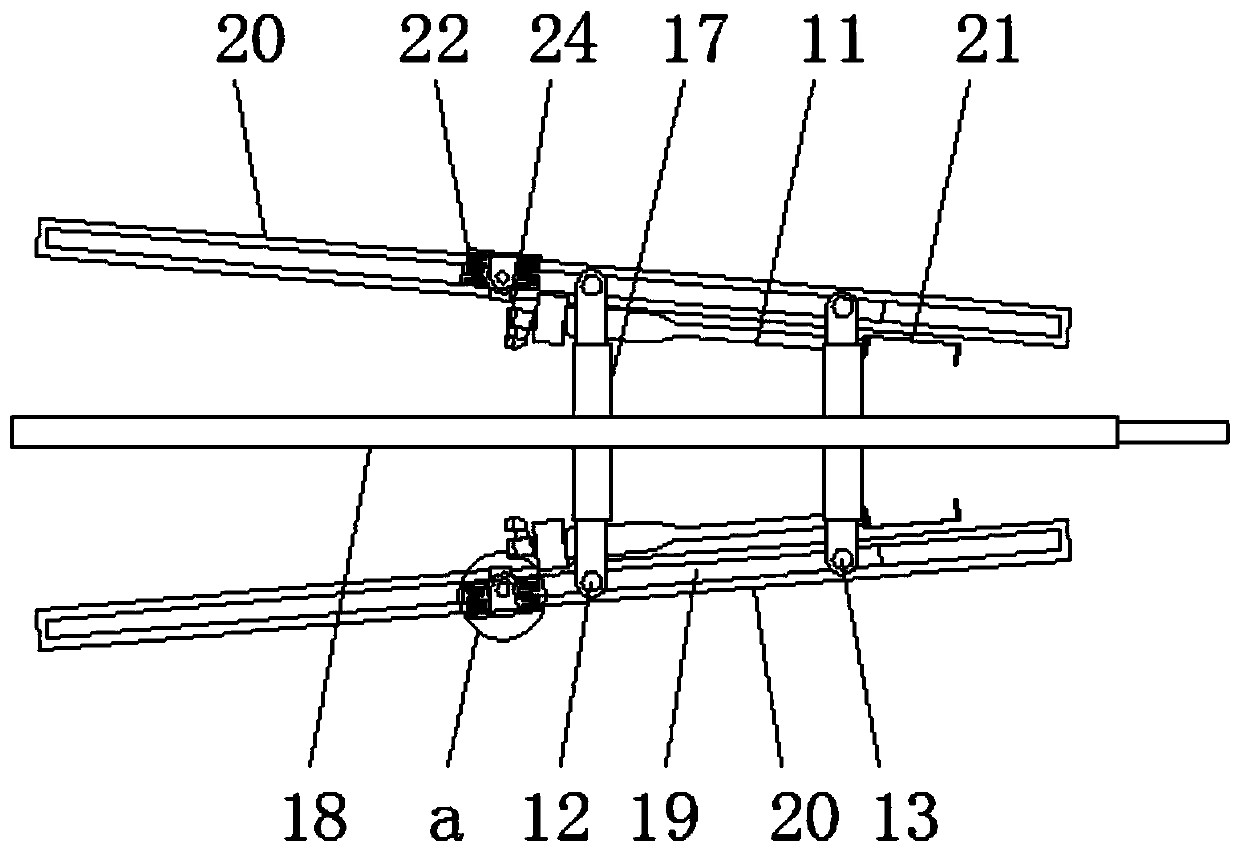
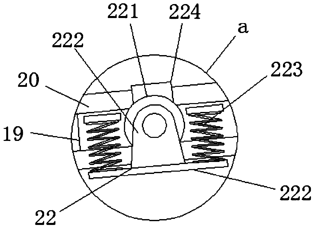
[0027] Such as Figure 1-Figure 7 As shown, a movable multi-pump nozzle structure applied to an air-jet loom includes a loom frame 1, a weaving mechanism 2, a moving wheel 3, a transmission spindle 4, a drive motor 5, a side drive cabinet 6, and an air pump Compressor 7, transmission pulley 8, bobbin support 9, weft feeder frame 10, fixed main nozzle 11, movable connecting rod 12, side movable rod 13, movable collar 14, support spring 15, movable seat 16, tele...


PUM


Abstract

The invention relates to a movable multi-pump nozzle structure applied to an air-jet loom. The structure comprises a loom rack, a transmission main shaft, a fixed main nozzle and a swing main nozzle;the transmission main shaft is located in the loom rack, an air pump compressor is arranged in a side drive cabinet, and a drive pulley is connected to a side end of the air pump compressor, a movableconnecting rod and a side movable rod are arranged on the outer side of the fixed main nozzle, telescopic movable beams are arranged at the upper ends of the movable connecting rod and the side movable rod respectively, a limiting sliding groove fits the outer side of a movable mounting base, and a movable limiting frame is arranged at the rear end of the fixed main nozzle. According to the movable multi-pump nozzle structure applied to the air-jet loom, the integrated side drive cabinet and the synchronously driven air pump compressor are arranged, by cooperating with the fixed main nozzle achieving flexible movement and adjustment for use, the structure compactness and use flexibility of the device can be improved, and maintenance operation is facilitated while stable operation is kept.

Description

technical field [0001] The invention relates to the technical field related to textile processing, in particular to a movable multi-pump nozzle structure applied to an air-jet loom. Background technique [0002] The loom needs to pull the weft yarn through the shed when processing the fabric, and weave it together with the warp yarn to form a complete fabric. Due to the limited traction speed of the traditional shuttle structure of the loom, more and more air-jet looms are used in existing textile processing. Such as shuttleless looms for textile production operations, air-jet looms can draw weft yarns through airflow, effectively improving weft insertion efficiency and increasing weft insertion rate. [0003] However, during the use of existing air-jet looms, multiple looms are generally directly supplied with air through the air supply station, which is not only inconvenient for the flexible use of a single loom, but the external air supply mechanism, bobbin frame and weft...

Claims


Application Information

Patent Timeline
Patent Type & Authority Applications(China)
IPC IPC(8): D03D47/30
CPCD03D47/30D03D47/3013D03D47/3053D03D47/308
Inventor 汪汉坤
Owner CHANGLE LIZHI IND DESIGN CO LTD
Why Eureka
Try Eureka