Centrifugal type anti- blocking rainwater inlet

A rainwater outlet and anti-clogging technology, which is applied to waterway systems, water supply devices, drainage structures, etc., can solve the problems of easy blockage and cleaning of rainwater outlets, inconvenience, etc., and achieve the effects of reducing labor operating costs, simple cleaning, and enhancing anti-clogging functions

Pending Publication Date: 2019-12-13
NANCHANG UNIV
View PDF10 Cites 6 Cited by
  • Summary
  • Abstract
  • Description
  • Claims
  • Application Information

AI Technical Summary

Problems solved by technology

[0006] The purpose of the present invention is to overcome the deficiencies of the prior art. The present invention provides a centrifugal anti-clogging gully, which solves the problem that the gully is easy to block and is inconvenient to clean.

Method used


Image

  • Centrifugal type anti- blocking rainwater inlet
  • Centrifugal type anti- blocking rainwater inlet
  • Centrifugal type anti- blocking rainwater inlet

Examples


Embodiment 1

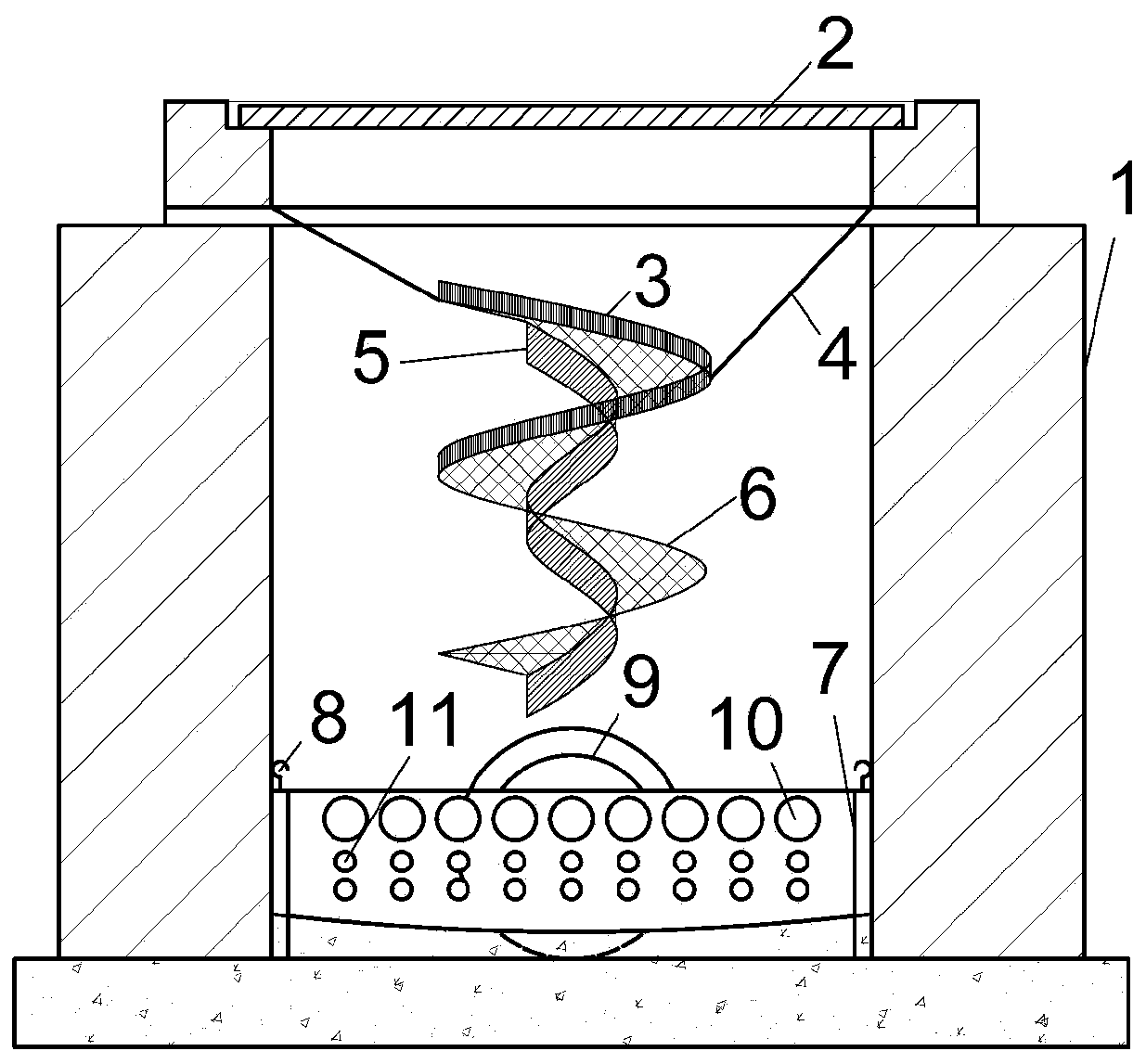
[0025] Embodiment 1, see figure 1 , a centrifugal anti-clogging gully, comprising a gully body 1, a gully grate 2, a baffle plate 3, a sling 4, a collection pipe 5, a spiral surface 6, a mud collecting tank 7, a hook 8, a rainwater pipe 9, Overflow large hole 10, overflow small hole 11.

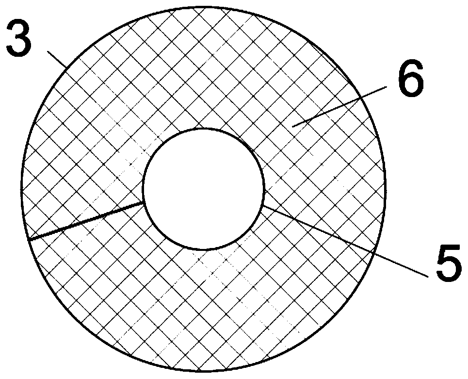
[0026] figure 2 It is a top view of the spiral separation device, image 3 It is a three-dimensional diagram of a spiral separation device, including a spiral curved surface 6 , a collection pipe 5 and a baffle 3 . During the rainy season, rainwater falls on the spiral curved surface 6, and forms a swirling flow under the action of the baffle plate 3 to prevent rainwater from splashing. The centrifugal force of the swirling flow will gather the sediment with a large specific gravity to the middle, and the rainwater with a small specific gravity will be thrown out of the spiral curved surface 6. The collected silt is introduced into the bottom silt collecting tank 7 through the middle coll...


PUM


Abstract

The invention relates to a centrifugal anti-blocking rainwater inlet. At present, the top surface of most of the rainwater inlet structures laid on a road is a rainwater well grate, the bottom is provided with a rainwater branch pipe to connect the rainwater well, and the rainwater well grate is provided with a plurality of apertures. When cleaning, it is easy to bring a fallen leaf and a sand stone into the rainwater well, and the sediment carried by the initial rainwater is also easy to deposit at the bottom of the rainwater well, so as to cause a blockage of a rainwater channel. The centrifugal anti-blocking rainwater inlet comprises a spiral curved surface, a collecting pipe, a baffle plate and a mud collecting groove. A swirl flow is formed through the convergence effect of the spiralcurved surface and the baffle plate, the separation of water and sediment is realized under the centrifugal force generated by the swirl flow, and the separated sediment is led into the mud collecting tank from the collecting pipe. Without affecting the drainage speed of the rainwater inlet, the centrifugal anti-blocking rainwater inlet effectively reduces the deposition of sediment in the rainwater pipe, reduces the burden of sewage interception, at the same time, it is convenient to install, the risk of the maintenance of the rainwater inlet of the pipe and the manual operation cost are reduced; a spiral separation device and the mud collecting groove are detachable, so that the intake and discharge are convenient.

Description

technical field [0001] The invention relates to the technical field of drainage, in particular to a centrifugal anti-clogging rainwater outlet. Background technique [0002] In recent years, due to various factors such as climate change and urban construction, urban waterlogging has occurred frequently, seriously threatening the safety of residents' lives and properties. In addition to the increase in extreme rainstorms, urban waterlogging is also particularly common due to reduced drainage capacity due to clogged storm drains and silted storm sewer pipes. The gully is the main subsidiary structure of the urban drainage pipeline system, and it is also an important part of urban road drainage. The rainwater outlet is located at the beginning of the urban drainage system, and is usually set at a certain distance from municipal roads, squares, street intersections and street gutters. The gully is the starting point of the urban drainage system, which has the function of colle...

Claims


Application Information

Patent Timeline
Patent Type & Authority Applications(China)
IPC IPC(8): E03F5/04
CPCE03F5/0401E03F5/0402
Inventor 陈战利李友皝季宏亮洪志成黄小华刘振中孙向荣
Owner NANCHANG UNIV
Why Eureka
Try Eureka