Concrete pouring device

A technology of concrete and conveying devices, which is applied in the direction of construction, building structure, and building materials processing, can solve the problems of increasing workload and materials, increasing worker workload, increasing construction time, etc., to reduce workload, Efficient pouring area range and the effect of improving work efficiency

Active Publication Date: 2019-12-13
陈忠海
View PDF8 Cites 4 Cited by
  • Summary
  • Abstract
  • Description
  • Claims
  • Application Information

AI Technical Summary

Problems solved by technology

At present, when concrete is conveyed and poured for buildings, the pump truck is usually used for concrete pouring, but the height of the pump truck pouring is limited, usually it can only pour a height of 5 floors at most, and in the process of conveying and pouring due to the secondary structure The working principle of the column pump causes the pipeline to vibrate strongly. It is not easy to fix the pipeline when erecting it, and another bracket must be erected to prevent the pipeline from vibrating. Many people are required to pull the pipe during pouring, and the pipe needs to be disassembled after pouring. The operation is cumbersome and inconvenient, which greatly increases the workload of workers, increases the construction time, and reduces work efficiency.

Method used


Image

  • Concrete pouring device
  • Concrete pouring device

Examples


Embodiment 1

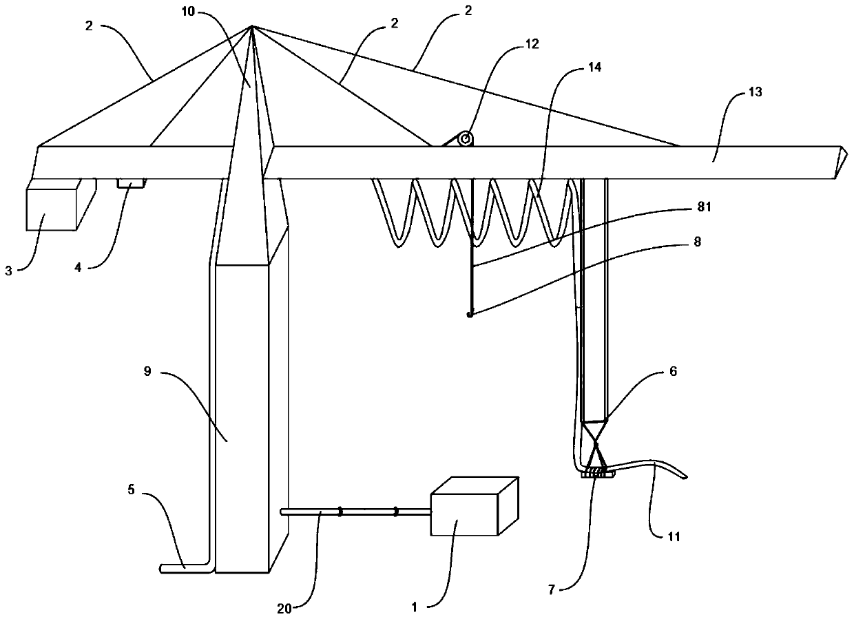
[0030] Such as figure 1As shown, a concrete conveying and pouring device in this embodiment includes a tower crane body, and a first conveying pipe for conveying concrete is arranged on the tower crane body. One end of the first conveying pipe is connected to a shock-absorbing conveying device, and the first conveying pipe A folded pipe 14 is provided at one end away from the shock-absorbing conveying device, and a concrete hose 11 is provided at the end of the folded pipe 14 away from the shock-absorbing conveying device.

[0031] The shock-absorbing conveying device is used to eliminate the vibration of the first conveying pipe during the concrete conveying process, prevent the folded pipe 14 from swinging during the concrete conveying process, and affect the stability of the tower crane body, resulting in inaccurate pouring positions and poor efficiency during concrete pouring. low. The folded pipe 14 is used to extend the first conveying pipe to further convey concrete, a...

Embodiment 2

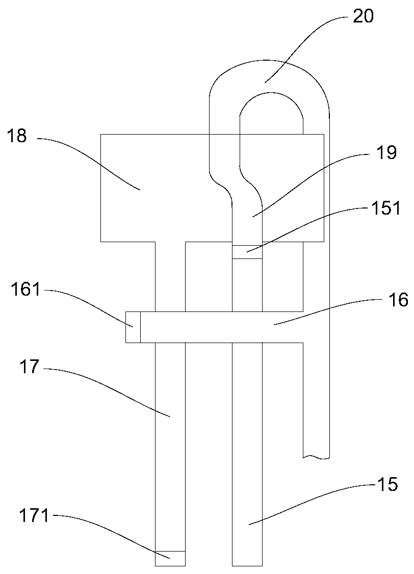
[0035] This embodiment is a definition optimized on the basis of the above-mentioned embodiment 1, such as figure 1 , figure 2 As shown, a concrete pouring device of this embodiment, the shock-absorbing conveying device includes a feed hopper 18 and a third cylinder 17 connected to the feed hopper 18, and the end of the third cylinder 17 away from the feed hopper 18 is provided with a first Three pistons 171; the feed hopper 18 is also provided with the first cylinder 15, the first cylinder 15 is positioned at one side of the third cylinder 17, and the first cylinder 15 is provided with the first piston 151 near the end of the feed hopper 18; The bucket 18 is provided with a guide tube 19, one end of the guide tube 19 is connected to the first cylinder 15, and the end of the guide tube 19 away from the first cylinder 15 is provided with a second delivery tube 20, and the second delivery tube 20 is far away from the feed hopper 18 One end of the second cylinder 16 is provided...

Embodiment 3

[0039] This embodiment is a definition optimized on the basis of the above-mentioned embodiment 1, such as figure 1 , figure 2 As shown, a concrete conveying and pouring device of this embodiment, the tower crane body includes a tower crane body 9 of a square structure, a tower crane cone 10 rotatably connected to the tower crane body 9 and a triangular beam frame arranged in the middle of the tower crane cone 10, the tower crane The conical body 10 is connected with the main body 9 of the tower crane through a rotating gear plate.

[0040] One end of the tower crane body 9 is connected to the ground, and one end of the tower crane body 9 away from the ground is connected to the tower crane cone 10 . In the middle of the connection between the tower crane main body 9 and the tower crane cone 10 is provided a pipe joint that can rotate 360 ​​degrees. Folding tube 14 is arranged through tower crane main body 9, and is arranged along the axial direction of tower crane main bod...


PUM


Abstract

The invention belongs to the technical field of concrete pouring, and discloses a concrete pouring device. The concrete pouring device includes a tower crane body, the tower crane body is provided with a folding pipe for conveying concrete, one end of the folding pipe is connected with a damping conveying device, and a concrete hose is arranged at the end, away from the damping conveying conveyor,of the folding pipe. According to the concrete pouring device disclosed by the invention, a tower crane is used for concrete pouring, in the process of pouring, high floors can be poured without theneed of building pipelines layer by layer manually, disassembling of the pipelines layer by layer is not needed after pouring, operation is easy, use is convenient, the range of high-efficiency concrete pouring is expanded, the work of needing to build a plurality of conveying pipe and materials are reduced, the workload of workers is greatly reduced, the working efficiency is advantageously improved, and the construction time is shortened. According to the damping conveying device, vibration of the conveying pipes during concrete conveying is eliminated, the folding pipe cannot swing freely in the conveying process, and the stability of the tower crane body is not affected.

Description

technical field [0001] The invention belongs to the technical field of concrete pouring, and in particular relates to a concrete pouring device. Background technique [0002] Concrete conveying and pouring refers to the process of conveying and pouring concrete into the mold by the secondary structure pump until it is plasticized. In civil engineering, materials such as concrete are conveyed into the mold to form a predetermined shape. At present, when concrete is conveyed and poured for buildings, the pump truck is usually used for concrete pouring, but the height of the pump truck pouring is limited, usually it can only pour a height of 5 floors at most, and in the process of conveying and pouring due to the secondary structure The working principle of the column pump causes the pipeline to vibrate strongly. It is not easy to fix the pipeline when erecting it, and another bracket must be erected to prevent the pipeline from vibrating. Many people are required to pull the ...

Claims


Application Information

Patent Timeline
Patent Type & Authority Applications(China)
IPC IPC(8): E04G21/04
CPCE04G21/0427E04G21/0454
Inventor 陈忠海
Owner 陈忠海
Why Eureka
Try Eureka