Attitude error compensation method of laser gyroscope dual-axis rotary inertial navigation system

A dual-axis rotation, inertial navigation system technology, used in navigation calculation tools, navigation through velocity/acceleration measurement, measurement devices, etc. question

Active Publication Date: 2019-12-13
BEIHANG UNIV
View PDF10 Cites 5 Cited by
  • Summary
  • Abstract
  • Description
  • Claims
  • Application Information

AI Technical Summary

Problems solved by technology

The deviation angle seriously reduces the attitude accuracy of the dual-axis rotary inertial navigation system. In order to overcome the influence of the deviation angle, the published patent CN104121926A proposes a calibration method for the installation error angle between the rotating shaft and the sensitive shaft of the dual-axis rotary inertial navigation system. The published patent CN109211269A proposes a method for calibrating the attitude error a

Method used


Image

  • Attitude error compensation method of laser gyroscope dual-axis rotary inertial navigation system
  • Attitude error compensation method of laser gyroscope dual-axis rotary inertial navigation system
  • Attitude error compensation method of laser gyroscope dual-axis rotary inertial navigation system

Examples


Embodiment Construction

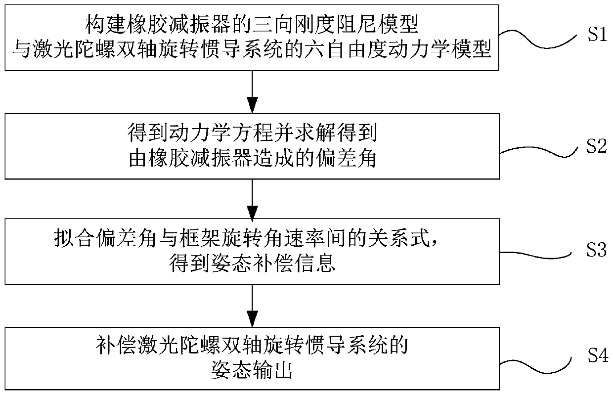
[0073] The present invention will be further described below in conjunction with accompanying drawing and specific embodiment, but following embodiment does not limit the present invention in any way.

[0074] Such as figure 1 As shown, by taking the 8 rubber shock absorbers between the laser gyro inertial measurement device and the inner frame of the dual-axis rotating mechanism in a laser gyro dual-axis rotary inertial navigation system as an example, the attitude error compensation method of the present application To describe the specific process, the specific steps are as follows:

[0075] S1. Construct a three-dimensional stiffness-damping model for each rubber shock absorber, replace eight rubber shock absorbers with eight three-dimensional stiffness-damping models, and build a six-degree-of-freedom dynamics model of the laser gyro dual-axis rotary inertial navigation system;

[0076] Specifically, the construction steps of the six-degree-of-freedom dynamic model in st...


PUM


Abstract

The invention discloses an attitude error compensation method of a laser gyroscope dual-axis rotary inertial navigation system. The attitude error compensation method is implemented by sequentially executing the following steps: constructing a six-degree-of-freedom kinetic model of the laser gyroscope dual-axis rotary inertial navigation system, obtaining a kinetic equation when an inner frame axis and an outer frame axis rotate, solving a deviation angle caused by the deformation of a rubber shock absorber when the inner/outer frame axis rotates by adopting a fourth-order Runge-Kutta method,and fitting the corresponding relationship between the angular rate of the frame axes obtained by dynamic analysis and the deviation angle caused by the deformation of the rubber shock absorber to obtain attitude error compensation information; and compensating the attitude output according to the attitude error compensation information. According to the attitude error compensation method, the attitude accuracy of the laser gyroscope dual-axis rotary inertial navigation system can be effectively improved; compared with the original uncompensated attitude output, the output accuracy of a pitching angle and a heading angle of the error-compensated attitude can be improved by about 8 times, and thus the effectiveness of the method can be fully proved.

Description

technical field [0001] The invention relates to the technical field of attitude error compensation of a rotary inertial navigation system, in particular to a method for attitude error compensation of a laser gyro dual-axis rotary inertial navigation system. Background technique [0002] The inertial measurement unit is the core component of the inertial navigation system. It provides the inertial device information of the carrier (the three-dimensional acceleration and three-dimensional angular velocity information relative to the inertial system) to the inertial navigation system through the three-axis gyro assembly and the three-axis accelerometer assembly installed orthogonally. . The navigation computer board of the inertial navigation system performs navigation calculation on the inertial device information to obtain the real-time navigation information of the carrier including position, velocity and attitude information. Since the navigation solution method of the ine...

Claims


Application Information

Patent Timeline
IPC IPC(8): G01C21/16G01C21/20G01C25/00
CPCG01C21/16G01C21/20G01C25/00
Inventor 蔡庆中涂勇强杨功流刘洋孙艺丁
Owner BEIHANG UNIV
Why Eureka
Try Eureka