Track fastener looseness detection method based on angle comparison

A track fastener and detection method technology is applied in the field of track fastener looseness detection based on angle comparison, which can solve the problems of limited application range, low efficiency, poor accuracy, etc., and achieve the effect of eliminating potential safety hazards in train operation.

Active Publication Date: 2019-12-13
成都精工华耀科技有限公司
View PDF14 Cites 4 Cited by
  • Summary
  • Abstract
  • Description
  • Claims
  • Application Information

AI Technical Summary

Problems solved by technology

[0007] The object of the present invention is to provide a method for detecting the loosening of track fasteners based on angle comparison. On the basis of not changing the structure of the existing fasteners, by judging whether the

Method used


Image

  • Track fastener looseness detection method based on angle comparison
  • Track fastener looseness detection method based on angle comparison
  • Track fastener looseness detection method based on angle comparison

Examples


Embodiment 1

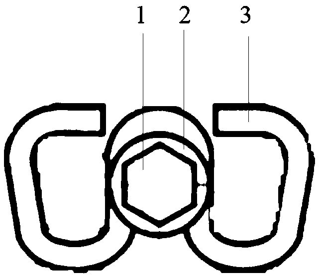
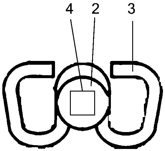
[0043] Embodiment 1 Determines whether the fastener is loose by measuring the angle value of the hexagonal bolt of the W-shaped fastener. In this embodiment, the W-shaped fastener using the hexagonal bolt is as follows: figure 2 As shown, the fastener includes a hexagonal bolt 1 , a bolt washer 2 and an elastic strip 3 .

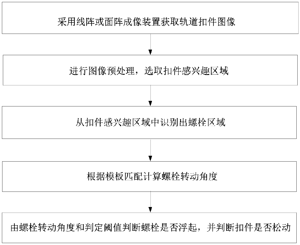
[0044]Step 1: Use a line array or area array imaging device to obtain the image of the rail fastener, and the optical axis of the line array or area array imaging device is perpendicular to the track road surface for imaging.

[0045] Step 2: Perform fastener image preprocessing, select the region of interest of the fastener, image preprocessing includes: image denoising, lens distortion correction of the imaging device, and transform the acquired fastener image into a bird's-eye view image according to the external parameters of the imaging device , to perform subsequent processing on the bird's-eye view image; when using a line scan imaging device to obta...

Embodiment 2

[0056] Different from Embodiment 1, the image matching method based on image edge similarity is adopted in step 4.2:

[0057] D=∑|S E (i,j)-T E (i,j)| (2)

[0058] Among them, S E (i,j) and T E (i, j) represent the edge at position (i, j) in the current detection image S and the template image T respectively, (i, j) represent the pixel coordinates of the overlapping area, ∑ represents the summation operation, D represents the matching degree, for Each angular rotation step extracts the overlapping area between the template image T and the current detection image S, and calculates the matching degree D according to formula (2). The smaller the D value, the greater the matching degree.

Embodiment 3

[0060] Steps 1 to 4 in Examples 1 and 2 are replaced by: using a 3D imaging system to obtain a 2D depth image of the fastener, performing bolt region segmentation on the 2D depth image, and performing bolt shape matching based on the 2D depth image, Calculate the bolt rotation angle, and the subsequent steps are the same as in Embodiments 1 and 2.

[0061] The area of ​​interest of the fastener selected in step 2 in Embodiments 1 and 2 can also be automatically detected in the preprocessed image by using methods such as SVM, deep learning, or neural network classification.

[0062] The bolts in Embodiments 1, 2 and 3 can also be replaced by nuts in the rail fastener.


PUM


Abstract

The invention discloses a track fastener looseness detection method based on angle comparison, and belongs to the field of railway infrastructure detection. The method mainly comprises the following main steps of acquiring a track fastener image by adopting a linear array or area array imaging device, carrying out image preprocessing, selecting a region of interest of a fastener, identifying a bolt region from the region of interest, carrying out template matching, computing a bolt rotation angle, judging whether a bolt rotates or floats according to a threshold angle, and then judging whetherthe track fastener is loose or not. The detection method provided by the invention is convenient to use, the structure of an existing railway fastener cannot be changed, and whether the track fastener is loose or not can be judged by detecting whether multiple types of fastener bolts or nuts rotate or float.

Description

technical field [0001] The invention relates to the field of railway infrastructure detection, in particular to a method for detecting loose rail fasteners based on angle comparison. Background technique [0002] The fastener is an important part connecting the rail and the sleeper. Its function is to fix the rail on the sleeper, maintain the gauge and prevent the rail from moving vertically and horizontally relative to the sleeper. Therefore, the fastener plays an important role in ensuring the stability and reliability of the track. play a very important role. Bolts and nuts are the key to ensure that the fasteners are firmly fixed. Once the bolts or nuts float, it will inevitably lead to loosening of the fasteners, which will cause serious safety hazards. [0003] In terms of railway infrastructure testing, my country has long been dominated by manual and static testing, with high maintenance costs, high strength, and poor safety. With the rapid development of high-speed...

Claims


Application Information

Patent Timeline
IPC IPC(8): G01M11/00
CPCG01M11/00
Inventor 左丽玛
Owner 成都精工华耀科技有限公司
Why Eureka
Try Eureka