Eureka AIR delivers breakthrough ideas for toughest innovation challenges, trusted by R&D personnel around the world.

An Improved Variational Mode Decomposition Method for Encoder Signal Analysis

A technique of variational mode decomposition and signal analysis, which is applied in the testing of machines/structural components, instruments, mechanical components, etc. It can solve problems such as short transmission paths, high fault sensitivity, and difficulty in working, so as to avoid selection Dependent, highly robust effects

Active Publication Date: 2021-02-02
BEIHANG UNIV
View PDF7 Cites 0 Cited by
  • Summary
  • Abstract
  • Description
  • Claims
  • Application Information

AI Technical Summary

Problems solved by technology

[0004] 1) High fault sensitivity: the gearbox meshing will produce obvious stiffness changes when passing through the fault area, and the encoder signal can directly reflect the torsional vibration behavior in the system, and is more sensitive to stiffness changes caused by faults
[0005] 2) The transmission path is short: the fault information needs to go through a complex and lengthy transmission path to be tested by the external vibration sensor
However, this method is only suitable for the situation where the noise content in the signal is small, and it is difficult to work under the interference of complex background noise

Method used


Image

  • An Improved Variational Mode Decomposition Method for Encoder Signal Analysis
  • An Improved Variational Mode Decomposition Method for Encoder Signal Analysis
  • An Improved Variational Mode Decomposition Method for Encoder Signal Analysis

Examples


Embodiment Construction

[0037] The present invention will be described in detail below in conjunction with the accompanying drawings and embodiments.

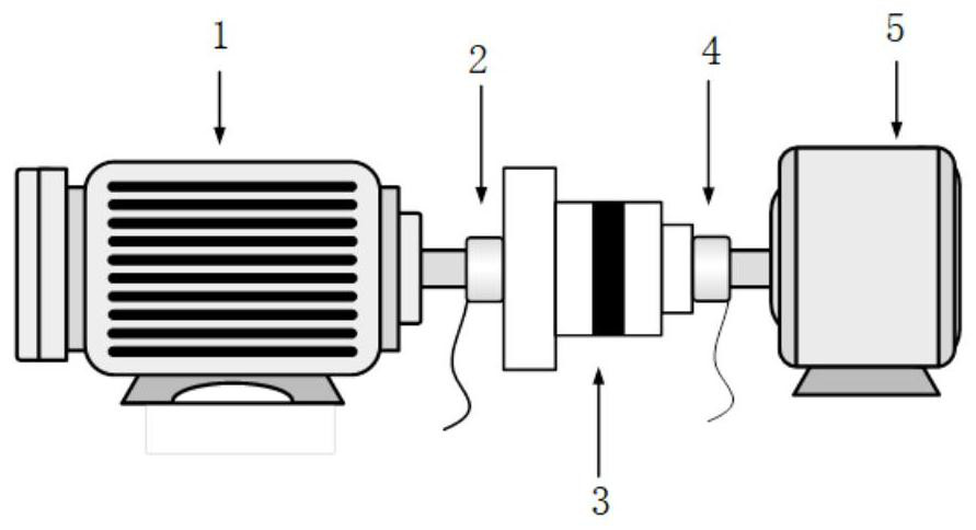
[0038] Taking the planetary gearbox test bench as an example, such as figure 1 The test bench shown is composed of drive motor 1, input shaft encoder 2, planetary gearbox 3, output shaft encoder 4, and brake 5, as shown in figure 1 shown. The input shaft encoder 2 is installed on the input shaft end of the planetary gearbox 3 , and the output shaft encoder 4 is installed on the output shaft end of the planetary gearbox 3 . The prefabricated planetary gear tooth surface spalling failure is placed in the planetary gearbox 3 for test experiments.

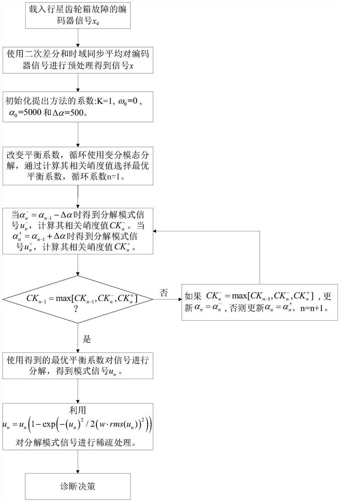
[0039] Such as figure 2 As shown, the improved variational mode decomposition method for encoder signal analysis includes the following steps:

[0040] Step 1: First use the output shaft encoder 4 to collect the encoder signal x of the output shaft of the gearbox e ,Such as image 3 as shown, image 3 ...


PUM


Abstract

The present application provides an improved variational mode decomposition method for encoder signal analysis, which includes: collecting the encoder signal x of the output shaft of the gearbox to the output shaft encoder e Perform processing to obtain the preprocessed signal x; initialize the input coefficient of the decomposition method; use the relative kurtosis value of the mode signal u during the decomposition process to select the appropriate balance coefficient; select the optimal balance coefficient by cyclically using the variational mode decomposition method; After the optimal balance coefficient is obtained, the corresponding decomposed signal is sparsely processed; the encoder signal after analysis is analyzed, and the fault diagnosis result of the gearbox is given according to the interval distance of the fault impact. The invention avoids the dependence of the traditional variational mode decomposition method on the selection of two parameters, the decomposition mode and the balance coefficient; it has high robustness and does not need to manually set parameters in the cycle process, and is suitable for online health monitoring.

Description

technical field [0001] The invention relates to the technical field of mechanical equipment fault diagnosis, in particular to an improved variational mode decomposition method for encoder signal analysis. Background technique [0002] Gearbox systems are key transmission components in rotating machinery. Its failure is the most important cause of mechanical equipment downtime and even accidents. Therefore, how to accurately diagnose gearbox faults has become one of the hottest topics in the field of mechanical fault diagnosis. Usually, the test method used for gearbox fault diagnosis is vibration analysis, because the state deterioration of mechanical equipment often manifests as changes or abnormalities in vibration information. However, due to the increasing integration of mechanical equipment, vibration-based analysis methods encounter difficulties in gearbox fault diagnosis. Therefore, finding a new test method to replace the traditional vibration analysis has become ...

Claims


Application Information

Patent Timeline
Patent Type & Authority Patents(China)
IPC IPC(8): G06F17/10G01M13/021
CPCG01M13/021G06F17/10
Inventor 林京苗永浩易迎港张博瑶
Owner BEIHANG UNIV
Why Eureka
Eureka Blog
Learn More