Capacitor insulation terminal cover

A technology for insulating terminals and capacitors, applied in the field of capacitors, can solve the problems of weak welding, large power supply creepage distance, falling off or virtual welding, etc., and achieve the effect of improving welding efficiency.

Active Publication Date: 2019-12-13
ANHUI SAFE ELECTRONICS
View PDF4 Cites 1 Cited by
  • Summary
  • Abstract
  • Description
  • Claims
  • Application Information

AI Technical Summary

Problems solved by technology

This traditional structure uses many parts with poor consistency, which is easy to cause large contact resistance, and the welding area of ​​the welding piece and the internal power line is small, which is easy to fall off or false welding, and when the welding piece is riveted, it is easy to cause Large spacing, resulting in large creepage distance of the power supply
The patent application document with the application number CN201410441563.4 protects a capacitor insulating terminal cover, but this structure has the following problems: (1) Due to the soft quality of the internal power cord, the inner core of the power cord and the connection There is a gap between the barrels. If the internal power line is not auxiliary fixed, the internal power line will fall during soldering, resulting in weak welding; (2) The use environment of the capacitor is complicated, and it is often subject to bumps or collisions. Once the thin waist drum-shaped soldering part is aged, it is easy to fall off from both ends of the connecting cylinder, which will affect the conductivity of the capacitor

Method used


Image

  • Capacitor insulation terminal cover
  • Capacitor insulation terminal cover
  • Capacitor insulation terminal cover

Examples


Embodiment

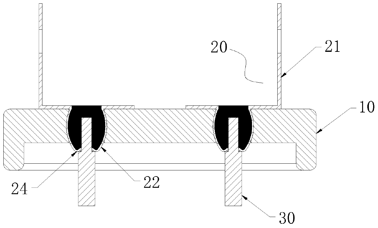
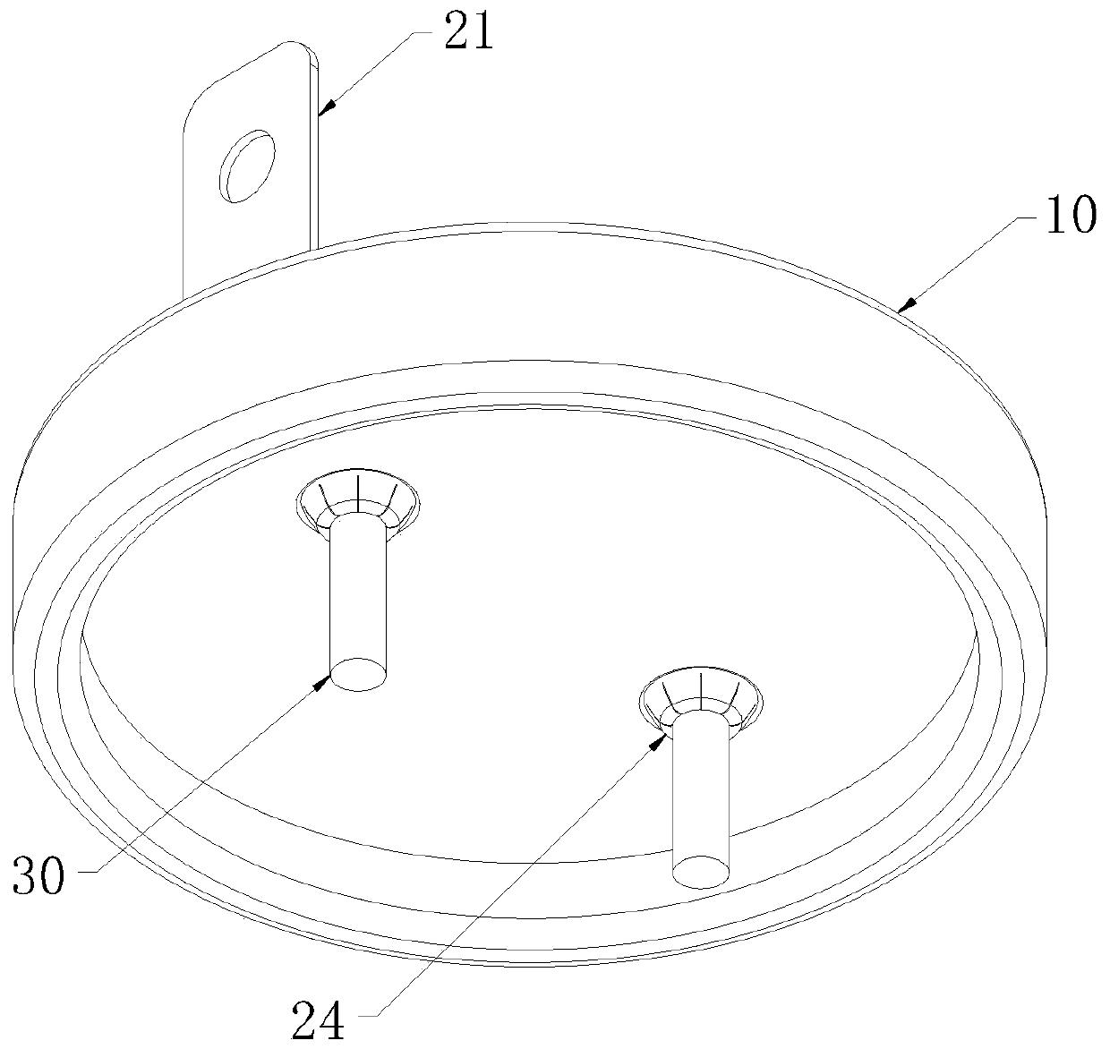
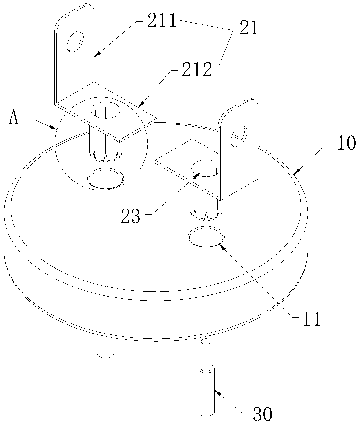
[0018] Such as Figure 1~3 As shown, the capacitor insulated terminal cover includes a cover plate 10 made of insulating material, a terminal 20 and a power line 30 arranged in the capacitor case. The connecting cylinder 22 at the bottom of the part 21, the connecting cylinder 22 is in the shape of a thick waist drum in the middle, the cover plate 10 is provided with a connecting hole 11 for inserting the connecting cylinder 22, and the connecting hole 11 is in the shape of the connecting cylinder 22 The same drum shape, the wiring part 21 includes a vertical part 211 connected to the external wire and a horizontal part 212 connected to the connecting cylinder 22, the horizontal part 212 is provided with a soldering hole coaxially arranged with the connecting cylinder 22 23. The bottom end of the connection cylinder 22 is provided with a bending portion 24 extending toward the center of the connection cylinder 22; the conductive core of the power cord 30 extends into the conne...


PUM


Abstract

The invention discloses a capacitor insulation terminal cover, which comprises a cover plate, a wiring terminal and a power line, wherein the wiring terminal comprises an L-shaped wiring part and a connecting cylinder, the connecting cylinder is in a waist drum shape with a thick middle part, the cover plate is provided with a connecting hole, the connecting hole is in the shape of a waist drum identical to that of the connecting cylinder, the wiring part comprises a vertical part connected with an external wire and a horizontal part connected with the connecting cylinder, the horizontal partis provided with a tin soldering hole coaxial with the connecting cylinder, and the bottom end of the connecting cylinder is provided with a bending part extending towards the center of the connectingcylinder; and the conductive core body of a power line penetrates through the bending part and extends into the connecting cylinder, and the conductive core body of the power line and the connectingcylinder are fixed through tin soldering filing. According to the capacitor insulation terminal cover, the problem that the tin soldering part is easy to fall off from the two ends of the connecting cylinder after being aged can be avoided; the conductive core body of the power line is fixed through the bending part, so that the complicated process of auxiliary fixing of the power line is avoided,and the welding efficiency is improved.

Description

technical field [0001] The invention belongs to the technical field of capacitors, in particular to a capacitor insulating terminal cover. Background technique [0002] Usually, the capacitor insulating terminal cover is formed by fixing the quick-connect terminal on the upper surface of the cover made of insulating material by rivets, and the rivet fixes the welding piece on the lower surface of the cover at the same time, through the welding piece and the inside of the capacitor. Solder the power cord. This traditional structure uses many parts with poor consistency, which is easy to cause large contact resistance, and the welding area of ​​the welding piece and the internal power line is small, which is easy to fall off or false welding, and when the welding piece is riveted, it is easy to cause The larger the spacing, the larger the creepage distance of the power supply. The patent application document with the application number CN201410441563.4 protects a capacitor i...

Claims


Application Information

Patent Timeline
IPC IPC(8): H01G4/224H01G4/228
CPCH01G4/224H01G4/228
Inventor 周峰
Owner ANHUI SAFE ELECTRONICS
Why Eureka
Try Eureka