Composite additive manufacturing method of conformal cooling die

A conformal cooling and additive manufacturing technology, applied in the field of additive manufacturing, can solve the problems of poor shape regularity of the upper arm of the cavity, rough inner wall, and low precision of the mold surface, so as to improve cooling performance, large heat source radius, cost and The effect of improving efficiency

Active Publication Date: 2019-12-17
SHENYANG INST OF AUTOMATION - CHINESE ACAD OF SCI
View PDF6 Cites 6 Cited by
  • Summary
  • Abstract
  • Description
  • Claims
  • Application Information

AI Technical Summary

Problems solved by technology

[0005] The processing efficiency of the injection mold can be greatly improved through the conformal cooling mold manufactured by additive manufacturing, but the surface precision of the mold produced by additive manufacturing is not high, and the required surface precision must be obtained through post-finishing and polishing.
At this stage, foreign researchers have also proposed that complex displacement technology can be used to realize the powder-feeding additive manufacturing technology to directly form the cavity structure of the mold, but the cavity structure manufactured by this method often has poor shape regularity of the upper arm of the cavity and irregular inner walls. smooth

Method used


Image

  • Composite additive manufacturing method of conformal cooling die
  • Composite additive manufacturing method of conformal cooling die
  • Composite additive manufacturing method of conformal cooling die

Examples


Embodiment 1

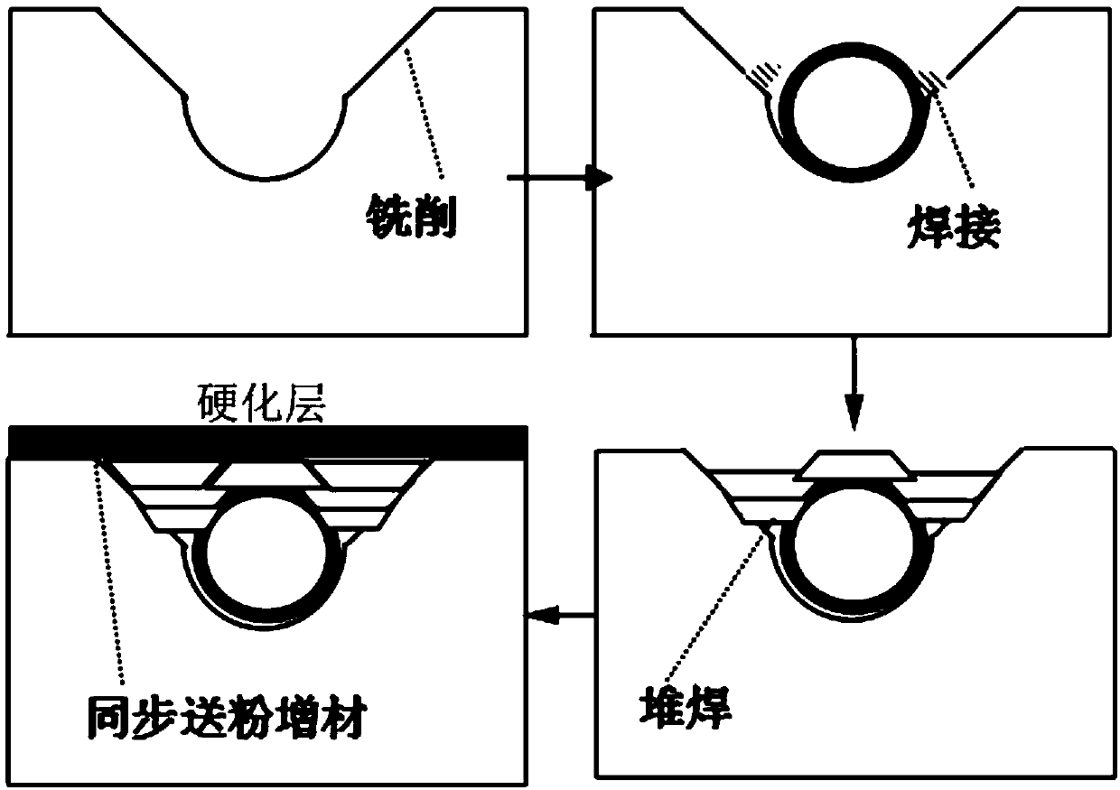
[0027] figure 1 It is a schematic diagram of the process flow of the present invention. The process mainly includes four processes of milling semicircular grooves and grooves on the substrate, welding positioning of pipes, surfacing filling, and laser synchronous powder feeding for additive manufacturing of the surface layer.

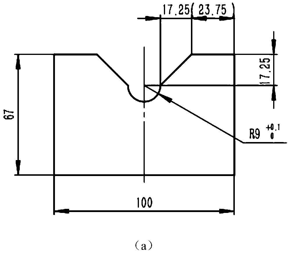
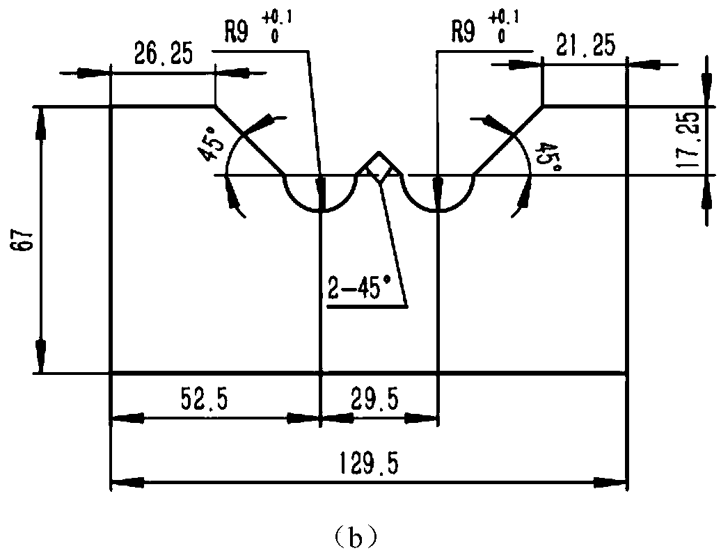
[0028] figure 2 It is the substrate processing groove and groove diagram of the present invention. A semicircular arc with the same diameter as the outer diameter of the cooling pipe is machined on the substrate, and then grooves are made on both sides of the arc. The base material is pre-hardened P20 forged material.

[0029] Place the stainless steel tube or the copper tube in the arc groove, use the fixture to position, and then use the argon arc welding to weld the tube to the base. The stainless steel pipe used in this embodiment is a 316L stainless steel pipe with a wall thickness of 3 mm.

[0030] Then, plasma arc additive manufacturing is used to su...


PUM


Abstract

The invention discloses a composite additive manufacturing method of a conformal cooling die, and belongs to the field of additive manufacturing. During the manufacturing process of a complex cavity structure, a pipe is adopted as a supporting condition. The composite additive manufacturing method comprises the following steps of at first, machining a circular arc-shaped trough, which is identicalto the external diameter of a cooling pipeline, in a forged base material in a numerical control manner, and forming grooves; placing the pipe in the trough, and performing welding orientation and fixing; swinging an additive manufacturing intermediate layer material in the direction perpendicular to the axial direction of the pipe by adopting a high-efficiency arc surfacing manner; and finally,milling a thick surface of a surfacing layer in a numerical control manner, and adopting a laser synchronous powder feeding process to form a compact and flawless hardened layer. The composite additive manufacturing method adopts a pipe positioning and supporting way, can realize invariable pose direct molding of a runner-containing structure, adopts a surfacing process in the manufacturing process of a large-size intermediate layer material additive, and can remarkably increase the additive speed.

Description

Technical field [0001] The invention belongs to the technical field of additive manufacturing, and specifically relates to a composite additive manufacturing method of conformal cooling molds. Background technique [0002] The current powder-feeding additive manufacturing is mainly used in the near-net-size forming of solid parts such as large structures and thin-walled structures. Due to its relatively high material utilization rate, small machining allowances after forming, and high process flexibility, the advantages are The application in aerospace and other fields is becoming more and more extensive, and compared with powder-spreading additive manufacturing, it can achieve complex cavity structure forming. However, the powder-feeding additive manufacturing additive process is often not possible for unsupported overhangs. [0003] At this stage, the mold structure represented by the injection mold has extremely high requirements for surface quality and cooling performance. To ...

Claims


Application Information

Patent Timeline
Patent Type & Authority Applications(China)
IPC IPC(8): B22F3/105B23P15/24B33Y10/00
CPCB23P15/24B33Y10/00B22F10/00B22F10/25Y02P10/25
Inventor 赵宇辉王志国赵吉宾高元聂长武
Owner SHENYANG INST OF AUTOMATION - CHINESE ACAD OF SCI
Why Eureka
Try Eureka