Crawler type driving walking support mechanism applicable to tunneling machine

A crawler-type, roadheader technology, which is applied to mine roof supports, mining equipment, earthwork drilling, etc., can solve the problems of small supporting area, difficulty in advancing or retreating of supporting devices, hurting people, etc., and achieve a large supporting area. Effect

Pending Publication Date: 2019-12-17
ZHOUKOU NORMAL UNIV
View PDF0 Cites 0 Cited by
  • Summary
  • Abstract
  • Description
  • Claims
  • Application Information

AI Technical Summary

Problems solved by technology

[0003] The safety problem of temporary support in excavation work is a technical problem that has plagued coal production for a long time. Since the roof cannot be supported in time and effectively after tunnel excavation, rocks from the roof will often fall and cause injury accidents. The current solution to this problem There are mainly two schemes. One is to use an airborne advanced temporary support device with a simple structure. This device is mostly installed directly above the cutting part of the roadheader and can move together with the roadheader. However, the support area of ​​this device is relatively small. The other is the non-airborne tunneling support device, which can move by itself and realize continuous tunneling and continuous support operations, but it mostly adopts the cross-stepping forward method. If the bottom plate is soft or uneven, it will make it difficult for the support device to move or retreat. During the movement of the support device, the support position may be deviated due to the difference in the left and right travel resistance.

Method used


Image

  • Crawler type driving walking support mechanism applicable to tunneling machine
  • Crawler type driving walking support mechanism applicable to tunneling machine
  • Crawler type driving walking support mechanism applicable to tunneling machine

Examples


Embodiment Construction

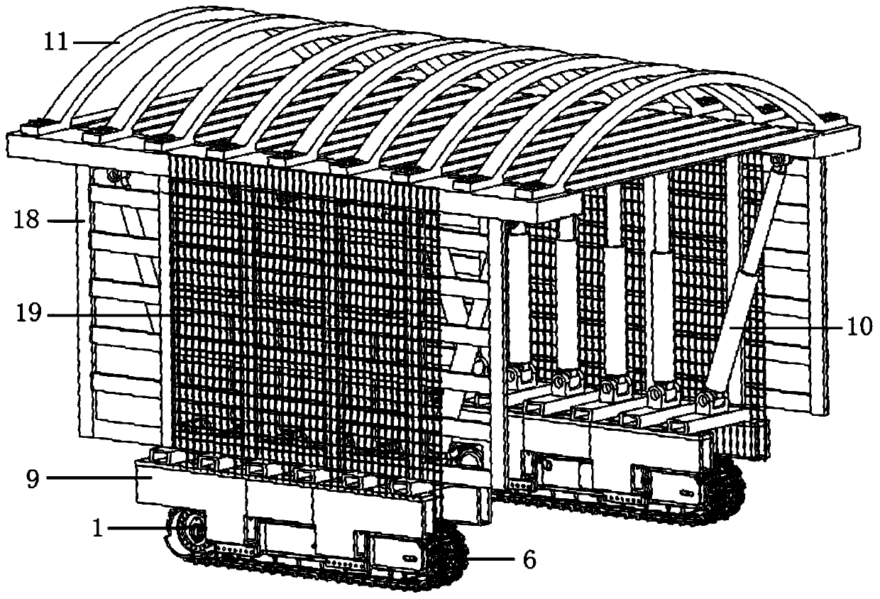
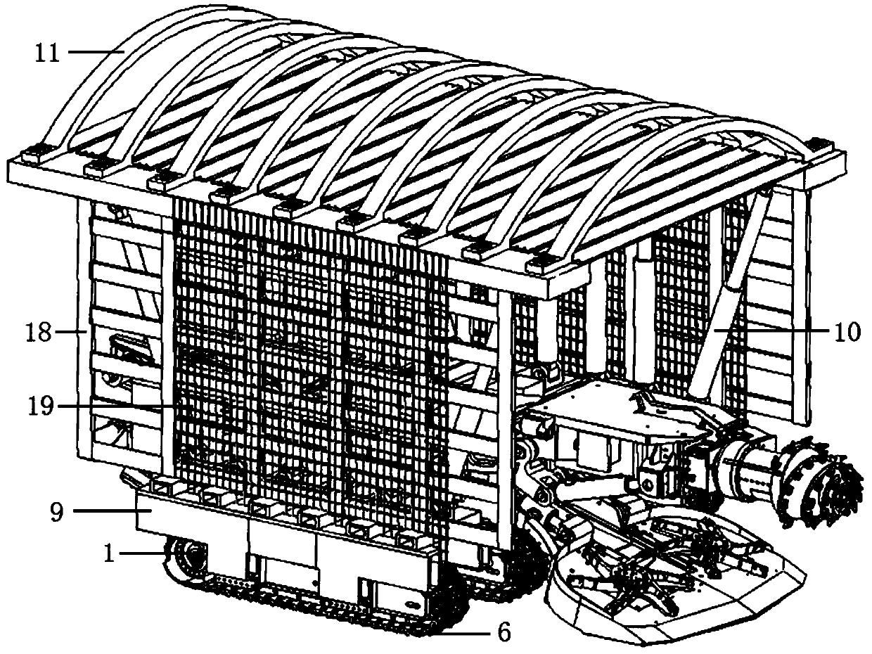
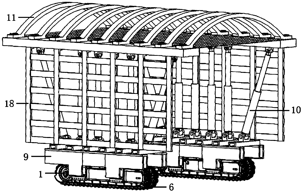
[0022] The present invention will be further described in detail below in conjunction with the accompanying drawings and specific embodiments.

[0023] Such as Figure 1-8 As shown, a crawler-type active walking support mechanism suitable for roadheaders includes a traveling part and a supporting part; the traveling part includes a hydraulic motor 1, a reducer 2, a sprocket 3, a tension wheel 4, and a support Wheel 5, track chain 6, wheel frame 7 and track chain friction plate 8; the hydraulic motor 1 and reducer 2 are installed on the front end of wheel frame 7, the power output end of hydraulic motor 1 and the power input end of reducer 2 The sprocket 3 is fixedly set on the power output end of the reducer 2; the tensioning wheel 4 is installed on the rear end of the wheel frame 7, and the tensioning wheel 4 and the sprocket 3 are connected by a track chain 6, so The number of supporting wheels 5 is several, and several supporting wheels 5 are installed side by side under t...


PUM


Abstract

The invention provides a crawler type driving walking support mechanism applicable to a tunneling machine. The support mechanism comprises a walking portion and a support portion. A hydraulic motor ofthe walking portion and a speed reducer are arranged at the front end of a wheel frame. The hydraulic motor is connected with the speed reducer. A chain wheel is connected with the power output end of the speed reducer. A tensioning wheel is arranged at the rear end of the wheel frame. The tensioning wheel and the chain wheel are connected through a crawler chain. A plurality of weight supportingwheels are arranged below the portion, between the tensioning wheel and the chain wheel, of the wheel frame. A crawler chain friction plate is arranged above the wheel frame. A supporting base of thesupport portion is fixedly installed on the wheel frame. Supporting oil cylinders are located between a supporting top beam and the supporting base. The supporting top beam comprises longitudinal beams, transverse beams and transverse plates. A plurality of transverse beams and transverse plates are fixedly installed between the two longitudinal beams in a striding manner. The two supporting oilcylinders located at the front-most end and the rear-most end in the tunneling direction are arranged obliquely. Other supporting oil cylinders are all arranged vertically. The supporting base and thewheel frame are fixedly connected by adopting an inserting connecting manner. A longitudinal protecting plate is arranged on the outer side of each supporting oil cylinder. A protecting net is installed on the outer surface of each longitudinal protecting plate in a hanging manner.

Description

technical field [0001] The invention belongs to the technical field of tunneling support equipment, in particular to a crawler-type active walking support mechanism suitable for tunneling machines. Background technique [0002] With the rapid development of coal mine fully-mechanized mining technology and equipment and mine supporting facilities, the mining intensity of fully-mechanized mining face has doubled, prompting the amount of excavation work in coal mine underground roadway to also increase dramatically. [0003] The safety problem of temporary support in excavation work is a technical problem that has plagued coal production for a long time. Since the roof cannot be supported in time and effectively after tunnel excavation, rocks from the roof will often fall and cause injury accidents. The current solution to this problem There are mainly two schemes. One is to use an airborne advanced temporary support device with a simple structure. This device is mostly install...

Claims


Application Information

Patent Timeline
IPC IPC(8): E21D23/04E21D23/18
CPCE21D23/04E21D23/18
Inventor 田震高珊张成光刘伟谢娟娟朱彬
Owner ZHOUKOU NORMAL UNIV
Why Eureka
Try Eureka