
Fatigue testing machine for rubber diaphragm

A technology of fatigue testing and rubber diaphragms, which is applied in the direction of applying repeated force/pulsation force to test the strength of materials, measuring devices, instruments, etc. It can solve the problems of reducing the service life of testing equipment, complex mechanical mechanisms, and fatigue of mechanical structures. Improve service life, reduce fatigue damage, and reduce the effect of mechanical transmission

Pending Publication Date: 2019-12-17
中广核高新核材科技(苏州)有限公司 +1
View PDF0 Cites 4 Cited by
  • Summary
  • Abstract
  • Description
  • Claims
  • Application Information

AI Technical Summary

Problems solved by technology

In the prior art, when performing fatigue tests on rubber diaphragms, the usual practice is to simulate the structure of the diaphragm pump and drive the rubber diaphragm through a series of mechanical linkage structures. On the one hand, the mechanical structure is complicated and the cost is high. On the other hand, the mechanical structure will also be fatigued. , reducing the service life of the test equipment

Method used


Image

  • Fatigue testing machine for rubber diaphragm
  • Fatigue testing machine for rubber diaphragm
  • Fatigue testing machine for rubber diaphragm

Examples


Embodiment Construction

[0020] The present invention will be further described below in conjunction with the accompanying drawings and specific embodiments, so that those skilled in the art can better understand the present invention and implement it, but the examples given are not intended to limit the present invention.

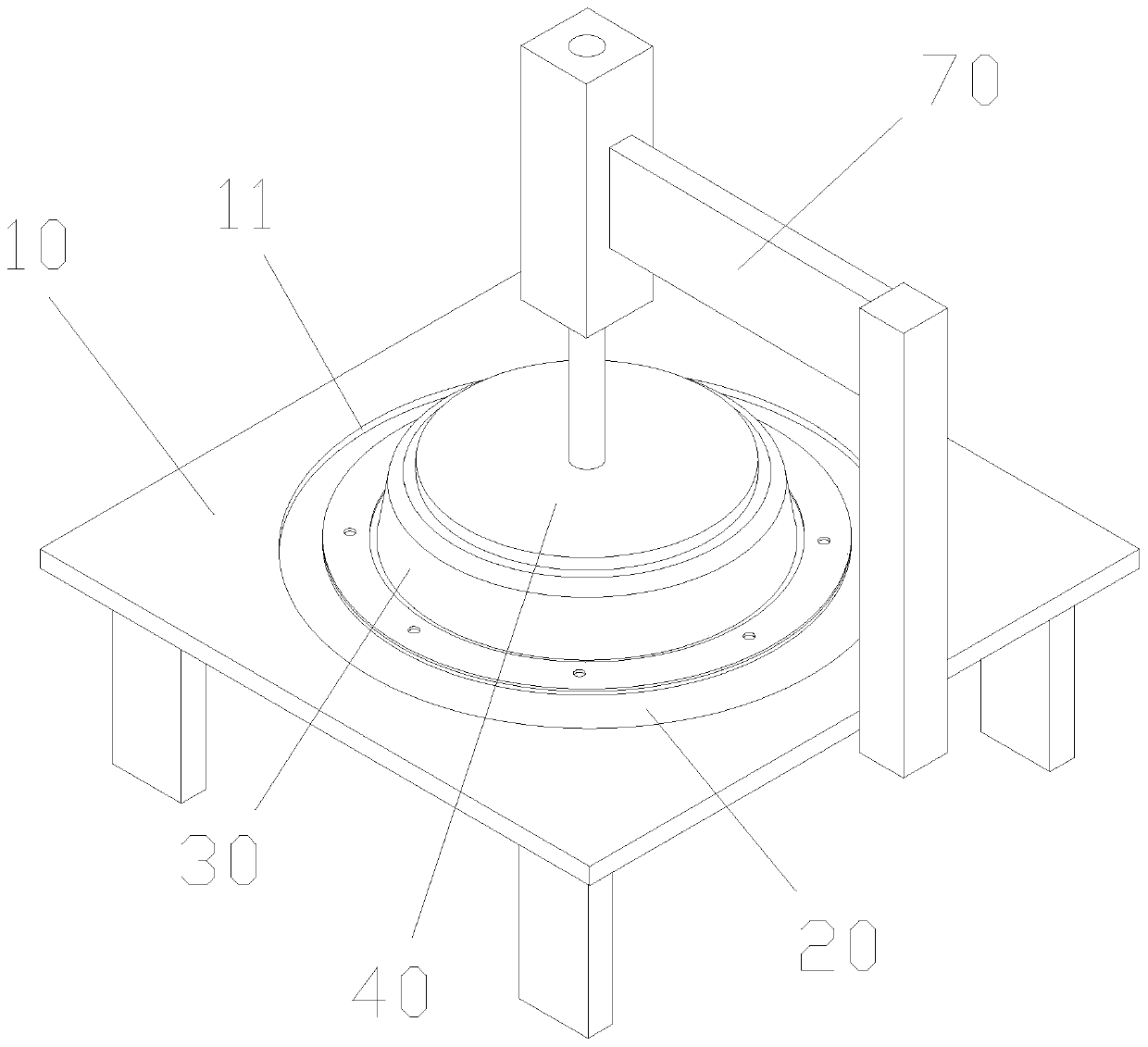
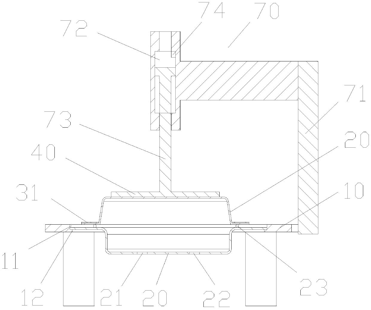
[0021] refer to figure 1 As shown, it is a schematic diagram of the overall structure of an embodiment of a fatigue testing machine for rubber diaphragms of the present invention. The surface of the support platform 10 is provided with a bayonet 11, the diaphragm 30 is arranged above the bayonet 11, the bottom support 20 is connected with the bayonet 11 and is located below the diaphragm 30, the diaphragm 30 is connected to the The bottom support 20 is sealed and connected, and a sealed space is formed between the diaphragm 30 and the bottom support 20. The bottom support 20 is provided with an air inlet 21 and an air outlet 22. The booster pump 50 is connected to the inlet throug...


PUM


Abstract

The invention discloses a fatigue testing machine for a rubber diaphragm. The fatigue testing machine comprises a bracket platform, a bottom support, a diaphragm, a pressing block and a booster pump,a bayonet is formed in the surface of the bracket platform, the diaphragm is arranged above the bayonet, the bottom support is connected with the bayonet and located below the diaphragm, the diaphragmis in sealed connection with the bottom support, an air inlet and an air outlet are formed in the bottom support, the booster pump is connected with the air inlet through an air inlet pipe, the air outlet is connected with an air outlet pipe, the air inlet pipe and the air outlet pipe are controlled by a control valve to be connected or disconnected, and the pressure block is placed above the diaphragm. Motion control over the diaphragm is achieved through inflation and deflation, resistance borne by the diaphragm is established through the pressing block, mechanical transmission is reduced,fatigue damage to the whole equipment is reduced, stable operation of the equipment is guaranteed, and the service life of the testing equipment is prolonged.

Description

technical field [0001] The invention relates to the technical field of rubber diaphragm testing equipment, in particular to a fatigue testing machine for rubber diaphragms. Background technique [0002] The rubber diaphragm is used in the pneumatic actuator of the valve of the automatic pipeline, and the diaphragm often fails due to fatigue due to frequent turning movements. Once the diaphragm fails, the air chamber of the pneumatic actuator cannot build pressure, and the valve stops working, causing The failure of the entire pipeline, especially for the continuous working environment required by nuclear power, chemical industry, water conservancy, etc., will cause significant losses. [0003] The rubber diaphragm is a vulnerable part, and the fatigue strength of the rubber diaphragm often determines the service life of the diaphragm pump after one repair. Therefore, the fatigue strength test of the rubber diaphragm has become one of the most important contents of the produ...

Claims


Application Information

Patent Timeline
Patent Type & Authority Applications(China)
IPC IPC(8): G01N3/36G01N17/00
CPCG01N3/36G01N17/00G01N2203/0019G01N2203/0005G01N2203/0044G01N2203/0073
Inventor 于广益成鹏马普东
Owner 中广核高新核材科技(苏州)有限公司
Learn More