
Wavelength conversion element, projection device and manufacturing method of wavelength conversion element

A technology for wavelength conversion components and manufacturing methods, which can be applied to projection devices, optical components, chemical instruments and methods, etc., can solve problems such as image brightness reduction, and achieve the effects of improving substrate softening and deformation, improving image brightness, and improving temperature resistance

Active Publication Date: 2019-12-17
CORETRONIC
View PDF5 Cites 1 Cited by
  • Summary
  • Abstract
  • Description
  • Claims
  • Application Information

AI Technical Summary

Problems solved by technology

[0008] The invention provides a projection device, which can improve the situation of image brightness degradation

Method used


Image

  • Wavelength conversion element, projection device and manufacturing method of wavelength conversion element
  • Wavelength conversion element, projection device and manufacturing method of wavelength conversion element
  • Wavelength conversion element, projection device and manufacturing method of wavelength conversion element

Examples


Embodiment Construction

[0024] The aforementioned and other technical contents, features and effects of the present invention will be clearly presented in the following detailed description of a preferred embodiment with reference to the drawings. The directional terms mentioned in the following embodiments, such as: up, down, left, right, front or back, etc., are only directions referring to the attached drawings. Accordingly, the directional terms are used to illustrate and not to limit the invention.

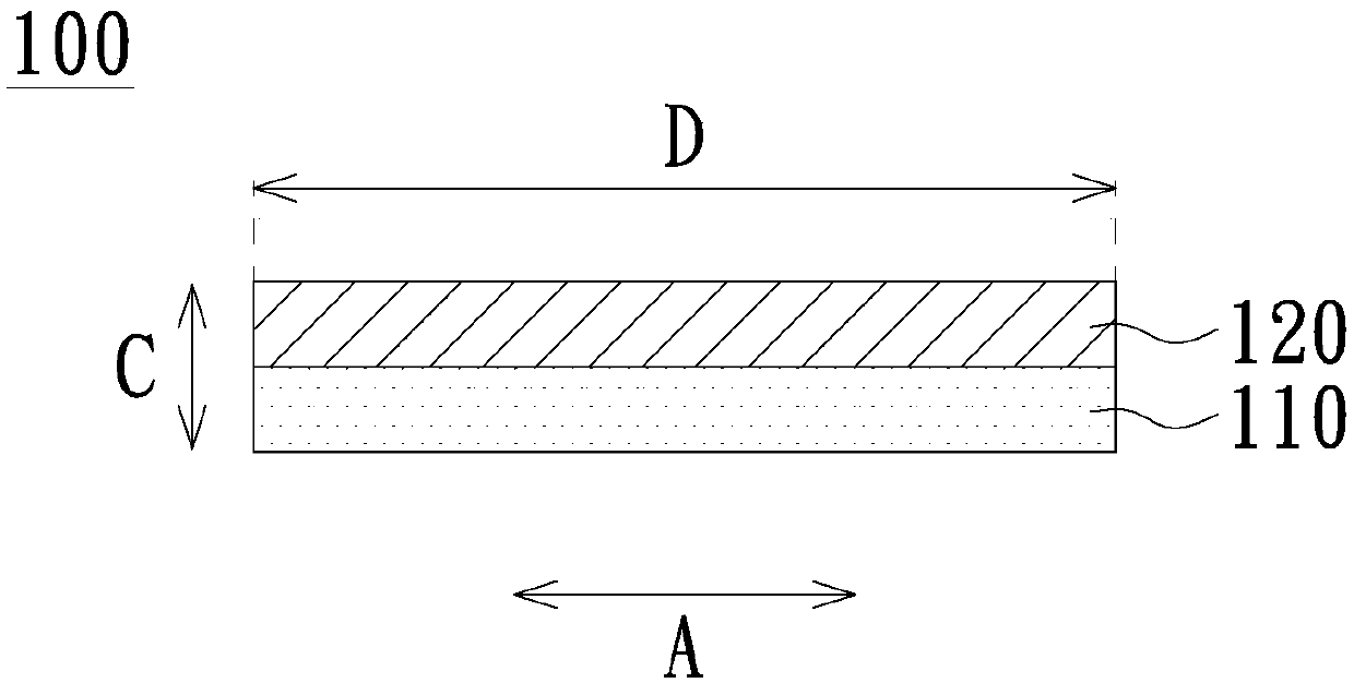
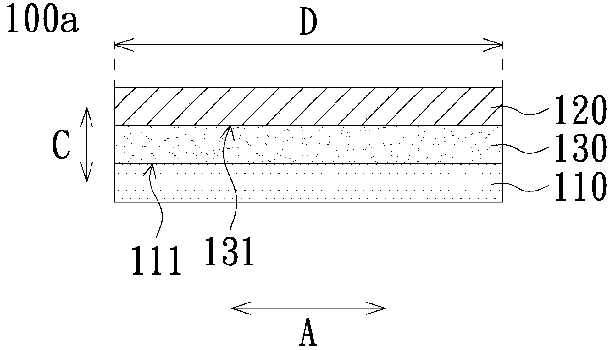
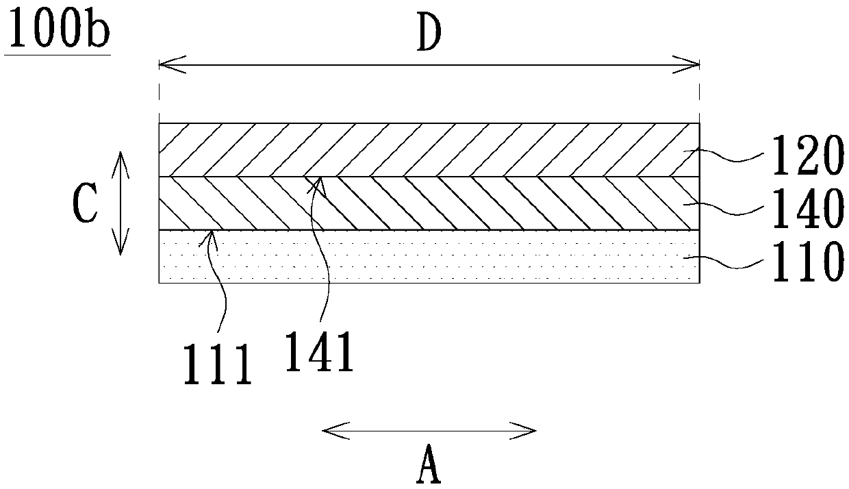
[0025] figure 1 is a schematic diagram of a wavelength conversion element according to an embodiment of the present invention. Please refer to figure 1 , the wavelength conversion element 100 of this embodiment includes a substrate 110 and a wavelength conversion layer 120 . The wavelength conversion element 100 is, for example, a plate element, but is not limited thereto. In other embodiments, the wavelength conversion element 100 may also be a wavelength conversion wheel, and the substrate 110 ...


PUM


Abstract

A wavelength conversion element comprises a substrate and a wavelength conversion layer. The wavelength conversion layer is disposed on the substrate. The wavelength conversion layer comprises a firstinorganic adhesive and a wavelength conversion material, wherein the wavelength conversion material are mixed in the first inorganic adhesive. The first inorganic adhesive comprises a first alcohol-soluble inorganic adhesive or a first water-soluble inorganic adhesive. The invention further provides a projection device using the wavelength conversion element and a manufacturing method of the wavelength conversion element.

Description

technical field [0001] The present invention relates to a display device, in particular to a wavelength conversion element, a projection device using the wavelength conversion element and a manufacturing method of the wavelength conversion element. Background technique [0002] The types of light sources used in projection devices have evolved from ultra-high pressure mercury lamps (UHP lamps) and light emitting diodes (light emitting diodes, LEDs) to Laser diode (laser diode, LD). [0003] At present, the cost of high-brightness red laser diodes and green laser diodes is too high. In order to reduce costs, blue laser diodes are usually used to excite the phosphors on the phosphor wheel to generate yellow and green light, and then pass through the color wheel (filterwheel) The required red light is filtered out, and then combined with the blue light emitted by the blue laser diode to form the three primary colors of red, green and blue required for the projection screen. ...

Claims


Application Information

Patent Timeline
Patent Type & Authority Applications(China)
IPC IPC(8): G03B21/20
CPCG03B21/204C09K11/02G03B21/2066C03C2218/154C03C17/007C03C2218/151G02B26/008
Inventor 陈怡华
Owner CORETRONIC
Learn More