

Method in connection with network converter, and network converter
- Summary
- Abstract
- Description
- Claims
- Application Information
AI Technical Summary
Benefits of technology
Problems solved by technology
Method used
Image

Examples
Embodiment Construction
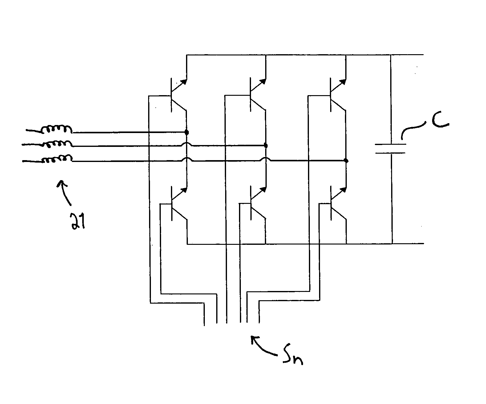
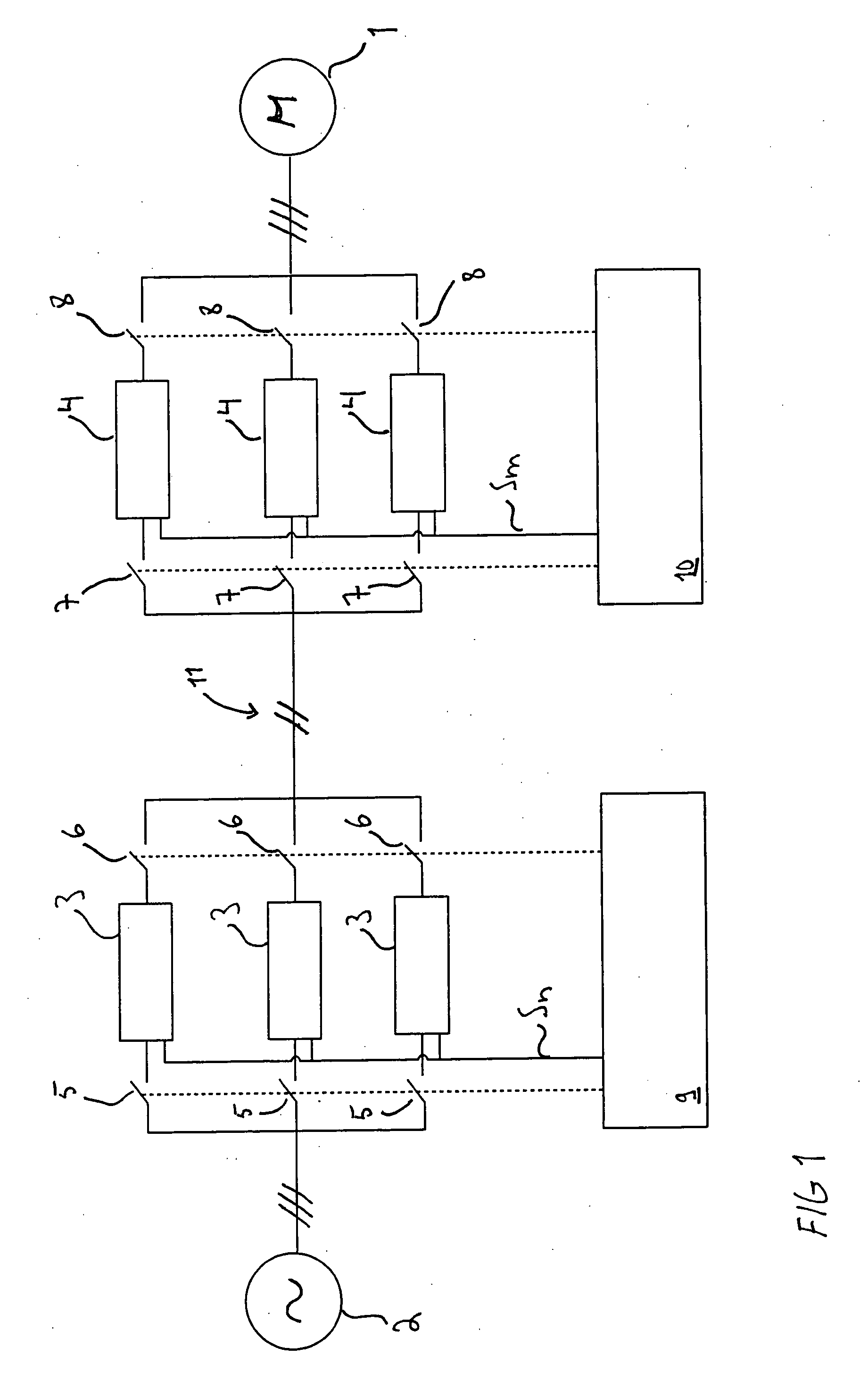
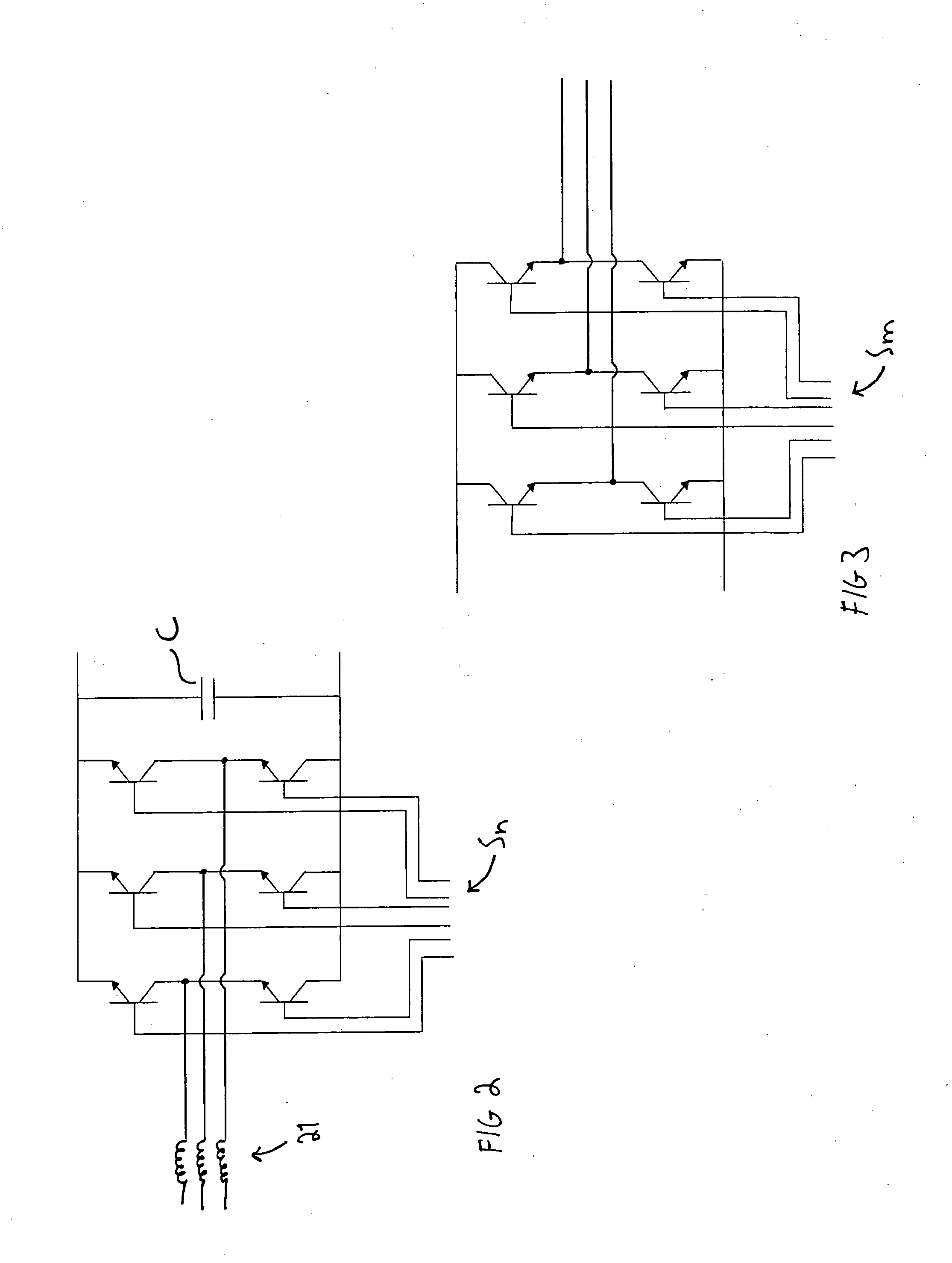
[0015]FIG. 1 shows a schematic structure of a frequency converter. In this structure, both a network converter and an inverter are modular. Use of the network converter according to the invention does not, however, necessarily require modularity of the inverter. The structure of a frequency converter is disclosed in FIG. 1 in connection with a motor drive, but in the specification reference is also made to a turbine drive wherein the motor 1 of FIG. 1 is used as a generator. FIG. 1 particularly shows a three-phase system wherein a frequency converter, according to the invention, is formed by three network converter modules 3 and three inverter modules 4 coupled in parallel. It is clear that the disclosed number of phases is not restricted to the example given in the figure; similarly, the number of parallel couplings of modules shown in the figure is not restricted thereto, either. Both may vary as necessary.
[0016]The frequency converter shown in FIG. 1 includes first control means ...
PUM
 Abstract
Description
Claims
Application Information