Lubricant oil distillation tank

A distillation tank and lubricating oil technology, which is applied in the field of lubricating oil, can solve problems such as the inability to achieve complete separation of oil and water, and achieve the effects of improving market applicability, improving utilization rate, and reducing waste

Active Publication Date: 2019-12-20
唐山浩昌杰环保科技发展有限公司
View PDF7 Cites 2 Cited by
  • Summary
  • Abstract
  • Description
  • Claims
  • Application Information

AI Technical Summary

Problems solved by technology

However, due to its degradable properties, the structure of base oil and additives is different from ordinary mineral hydraulic oil
[0003] When making bio-lubricating oil, when the polyol ester is put into the distillation tank for vacuum distillation and hydrogen peroxide is added for static stratification, when the existing distillation tank discharges the water in the lower layer, it will When the liquid is discharged from the retort, since the remaining height of the water level is not known, the staff can promptly and quickly close the discharge port at the bottom of the retort when a part of the oil is discharged to prevent the waste of oil. At the same time, it cannot Realize the complete separation of oil and water; in view of this, the present invention provides a lubricating oil distillation tank, which can automatically close the outlet after the water is discharged, reducing the waste of resources

Method used


Image

  • Lubricant oil distillation tank
  • Lubricant oil distillation tank
  • Lubricant oil distillation tank

Examples


Embodiment Construction

[0022] In order to make the technical means, creative features, goals and effects achieved by the present invention easy to understand, the present invention will be further described below in conjunction with specific embodiments.

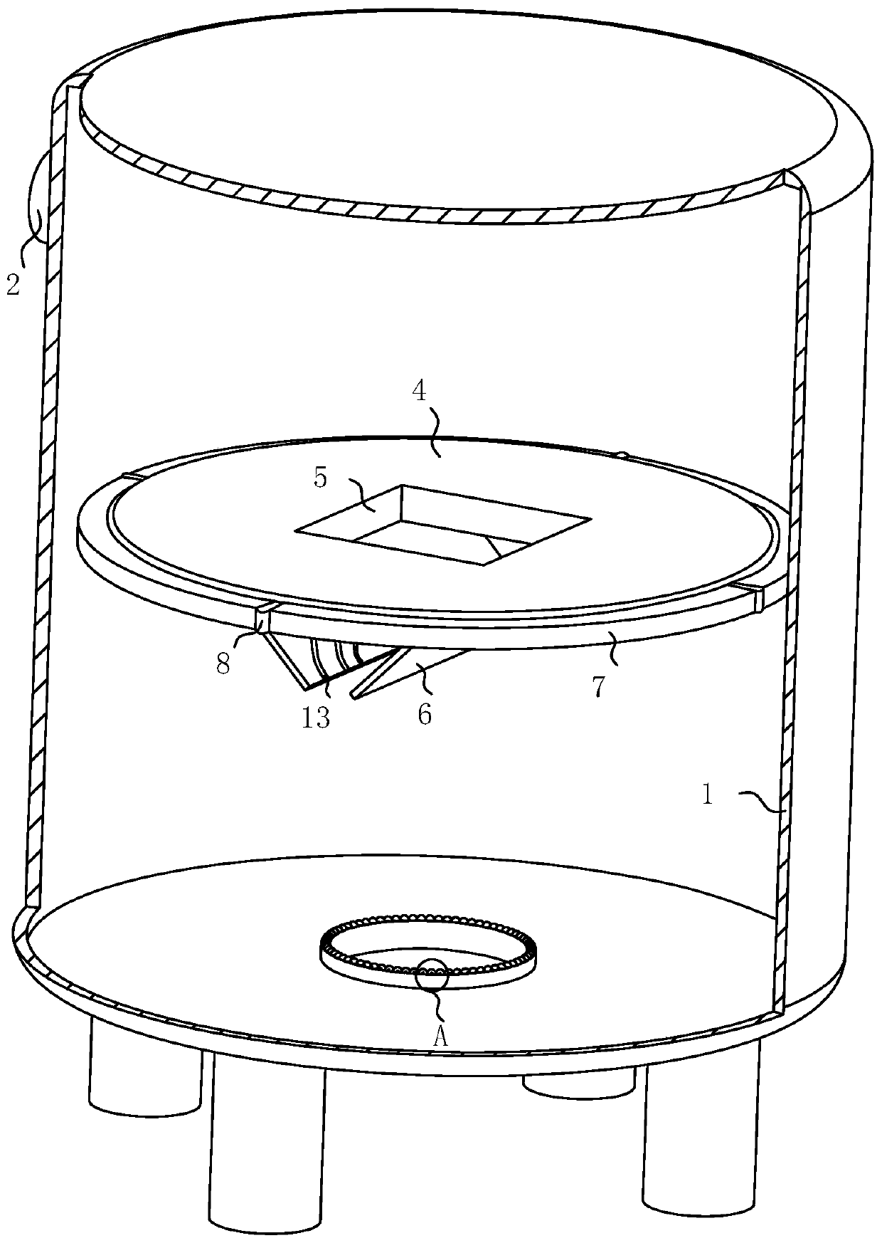
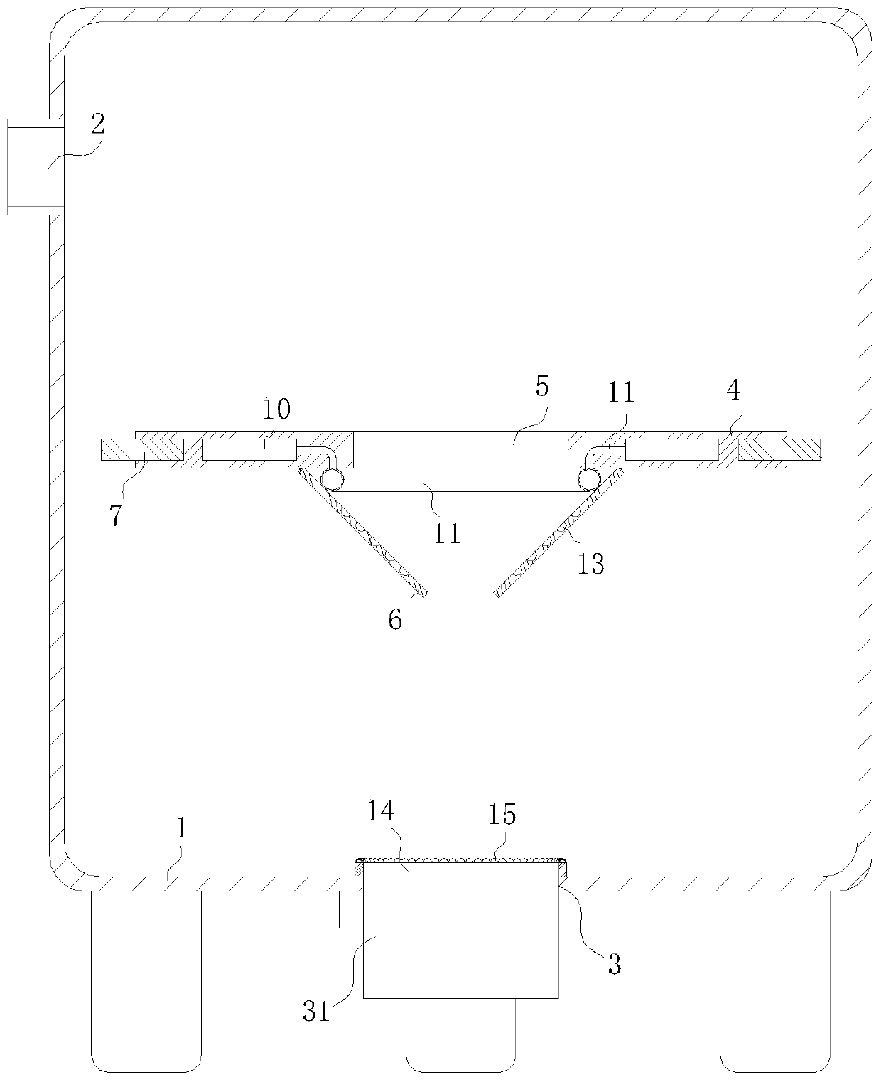
[0023] like Figure 1-4As shown, a lubricating oil distillation tank according to the present invention includes a tank body 1, the side wall of the tank body 1 is provided with a feed port 2, and the bottom of the tank body 1 is provided with a discharge port 3; The middle part of the inner side of the body 1 is provided with a moving plate 4, the moving plate 4 is made of light material, and a plurality of cavities are arranged inside, so that it can be suspended on the water surface and sink to the bottom of the polyol ester; the moving plate 4 The middle part is provided with a square through hole 5, and the surface of the moving plate 4 at the bottom of the square through hole 5 is hinged with two sealing plates 6, and the free ends of the tw...


PUM

PropertyMeasurementUnit
heightaaaaaaaaaa

Abstract

The invention belongs to the technical field of lubricant oil and particularly relates to a lubricant oil distillation tank. The distillation tank comprises a tank body, wherein a charging opening isformed in the sidewall of the tank body, and a discharging opening is formed in the bottom of the tank body; and a moving tray is arranged at the middle part of the inner side of the tank body and ismade from a lightweight material, a plurality of cavities are formed inside the moving tray, and thus, the moving tray can suspend on the water surface and sink to the bottom of a polyol ester. According to the lubricant oil distillation tank, the moving tray is arranged and is made from the lightweight material, the cavities are formed inside the moving tray, and the moving tray just suspends ata parting of water and the polyol ester after a certain amount of polyol ester is layered, so that the moving tray reaches the bottommost end when the water is discharged from the discharging opening,weight of the polyol ester above will apply a downward extruding force on the moving tray, finally, the moving tray extrudes two closing plates, thus, the two closing plates are in a contact state and block off a square through hole, finally, the automatic closing of the discharging opening is achieved, and wasting of resources is lowered.

Description

technical field [0001] The invention belongs to the technical field of lubricating oil, in particular to a lubricating oil distillation tank. Background technique [0002] Bio-lubricating oil is an ultra-clean lubricating oil that protects the environment from air pollution and also has the ability to reduce CO 2 Emissions reduce the characteristics of the greenhouse effect; the development of bio-lubricating oil is conducive to increasing production and improving the diesel / gasoline ratio of my country's oil structure. Hydraulic transmission technology is a transmission technology that is widely used in industry, but most of the current hydraulic systems The use of mineral hydraulic oil as the working medium not only consumes a large amount of oil resources, but also causes environmental pollution. Under this background, countries all over the world are researching environmental protection and energy-saving hydraulic transmission technology, and its main development directi...

Claims


Application Information

Patent Timeline
Patent Type & Authority Applications(China)
IPC IPC(8): B01D3/02B01D17/02C10M177/00
CPCB01D3/02B01D17/02C10M177/00
Inventor 王俊玉周典航刘德强
Owner 唐山浩昌杰环保科技发展有限公司
Why Eureka
Try Eureka