Three-dimensional vision-based fish tank cleaning robot motion control device and control method

A technology for cleaning robots and robot motion, applied in the direction of program control manipulators, instruments, manipulators, etc., can solve problems such as inability to accurately perceive, inability to do, and poor adaptability

Pending Publication Date: 2019-12-20
青岛森科特智能仪器有限公司
View PDF0 Cites 6 Cited by
  • Summary
  • Abstract
  • Description
  • Claims
  • Application Information

AI Technical Summary

Problems solved by technology

[0003] The second type of fish tank robot is obviously more advanced, but it also has the following disadvantages: 1. The robot cannot accurately perceive the location of obstacles such as water pipes, heating rods, rockeries, aquatic plants, etc. in the fish tank and the distance from the robot, and cannot achieve high success. 2. Relying on inertia, collision switches, infrared sensors and other methods to detect the relative position of the fish tank, it is impossible to accurately detect the position of the robot in the fish tank and the distance from each fish tank wall; 3. When the fish tank is large, The power charged by the robot at one time is not enough to wipe the entire wall of the fish tank. Since it cannot accurately sense the relative position of the fish tank, it cannot do accurate breakpoint continuous wiping; 4. The robot encounters the circulating water flow in the fish tank In case of impact, it will enter a blocked state where it cannot continue to automatically scrub, and cannot automatically judge and respond to various situations that hinder the movement of the robot. The adaptability is poor; 5. There are many types of sensors for the robot, and the design and assembly process is complicated and the cost is high. , it is difficult to produce

Method used


Image

  • Three-dimensional vision-based fish tank cleaning robot motion control device and control method
  • Three-dimensional vision-based fish tank cleaning robot motion control device and control method
  • Three-dimensional vision-based fish tank cleaning robot motion control device and control method

Examples


Embodiment 1

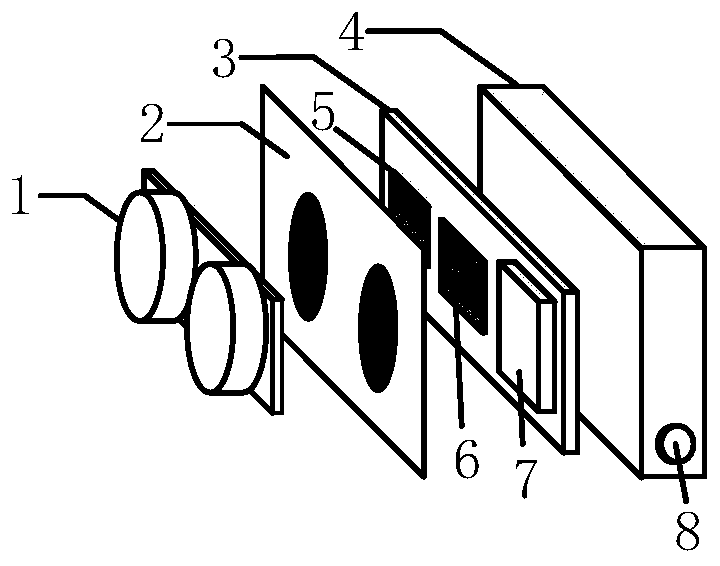
[0033] Example 1, as figure 1 As shown, this embodiment discloses a motion control device for a fish tank cleaning robot based on three-dimensional vision. The control device includes a front panel 2 and a rear panel 4, and the front and rear panels can be assembled together to form a shell of the control device; A binocular vision module 1 is installed in the housing, the lens of the binocular vision module protrudes out of the front panel, and a circuit board 3 is also installed in the housing, and the central processing unit CPU5, the graphics processing unit GPU6 and the communication board are arranged on the circuit board. Module 7, the above-mentioned binocular vision module, GPU and communication module are all electrically connected to and controlled by the CPU, and a power supply interface 8 for supplying power to various components in the control device is installed on the rear panel. The core components of the control device are a binocular vision module with three...


PUM


Abstract

The invention discloses a three-dimensional vision-based fish tank cleaning robot motion control device and a control method. The control device comprises a front panel and a rear panel, wherein the front panel and the rear panel can be assembled together to form a shell of the control device, a binocular vision module is arranged in the shell, a lens of the binocular vision module extends out ofthe front panel, a circuit board is arranged in the shell, a central processing unit, a graphics processing unit and a communication module are arranged on the circuit board, the binocular vision module, the graphics processing unit and the communication module are electrically connected with the central processing unit and are controlled by the central processing unit, and a power supply port forsupplying power to components in the control device is arranged on the rear panel. According to the control device, the computer binocular vision technology and the digital image processing algorithmare combined and applied to the motion control of a fish tank cleaning robot, and when the fish tank cleaning robot is in a fish tank, the precise position of the robot and the distance between the robot and an obstacle can be calibrated and the motion state of the robot can be judged.

Description

technical field [0001] The invention belongs to the field of underwater cleaning robots, and particularly relates to a motion control device and a control method for a fish tank cleaning robot based on three-dimensional vision in the field. Background technique [0002] The existing fish tank cleaning robots are divided into two types: one is magnetic suction, the robot is outside the fish tank, and the scrubbing device is inside the fish tank, and the two are attracted together through a permanent magnet through the glass. This kind of robot can only scrub one side of the fish tank, it cannot automatically change direction, and it cannot scrub the bottom of the fish tank. The other is that it can move freely like an AUV in the fish tank, and perform energy supplementation and data interaction through wireless charging and wireless communication. There are gyroscopes, accelerometers, water outlet detection electrodes, collision detection, distance detection, and speed wheels...

Claims


Application Information

Patent Timeline
Patent Type & Authority Applications(China)
IPC IPC(8): B25J9/16B25J13/00B25J19/04A01K63/10G06T7/73G06T5/00G06T7/10G06T7/13
CPCA01K63/10B25J9/16B25J13/00B25J19/04G06T5/006G06T7/10G06T7/13G06T7/73
Inventor 于敬东江文亮綦声波
Owner 青岛森科特智能仪器有限公司
Why Eureka
Try Eureka